S3 Series UL Listing Document — P/N LS10005-051GF-E:D3 3/09/2016 41
E3BB-FLUSH-LCD Cabinet A2 Assembly Installation Wiring
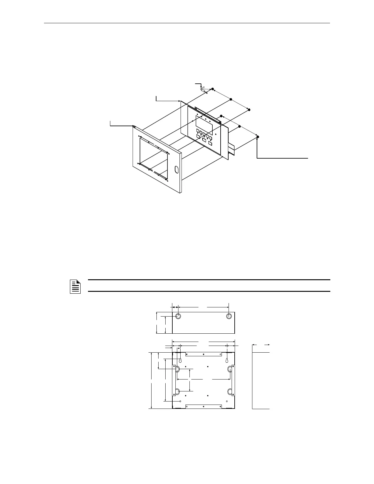
2.18.1.2 E3 Series Cabinet A2, Sub-Assembly to the Inner Door Installation
Figure 2.18.1.2.1 illustrates the LCD-SLP remote annunciator connected to the E3 Series Cabinet A2 inner
door installation.
1. To connect the LCD-SLP to the inner door, insert and secure four, #6-32 nuts in the four-hole mounting pattern as
shown in Location 1 in the figure below. The LCD-E3 may be installed in Cabinet A2.
2. Secure the opposite end of the bonding wire to the welded #6 stud on the inner side of the inner door
using the #6 nut as shown in Location 2 in the figure below.
Figure 2.18.1.2.1 E3 Series Cabinet A2, Sub-Assembly to the Inner Door Installation
2.19 E3BB-FLUSH-LCD Cabinet A2 Assembly
The E3 Series, E3BB-FLUSH-LCD Cabinet A2 assembly (Part Number: E3BB-FLUSH-LCD) typically
houses the following units:
• Backbox
• Outer Door
• Hardware Kit
2.19.1 E3BB-FLUSH-LCD Cabinet A2 Installation
Figure 2.19.1.1 illustrates the E3 Series, E3BB-FLUSH-LCD Cabinet A2 dimensions.
LCD-SLP
(P/N: 11200937)
NUT, (#6-32, HEX, KEPS)
(P/N: 36045) (6 PLACES)
LCD-SLP MODULE TO
S3 DOOR MOUNTING
BONDING
WIRE
2
1
1
1
1
CABINET A2,
INNER DOOR
– LCD-SLP Display Panel – LCD-E3 (Optional)
NOTE: Use the Hardware Kit provided with the E3BB-FLUSH-LCD, Cabinet A2 assembly.
Figure 2.19.1.1 E3BB-FLUSH-LCD Cabinet A2 Dimensions
BACKBOX
13 1/4"
9 27/32"
1"
1 45/64"
3"
1 13/64"
10" 7 1/2"
4" 11 1/4"
BACKBOX TOP
10 ¾”
1 1/4”
3 5/8”
4 1/2”
4 1/2"
1 45/64"
12
43

 Loading...


