S3 Series UL Listing Document — P/N LS10005-051GF-E:D3 3/09/2016 49
SLP Main Board Features Functionality
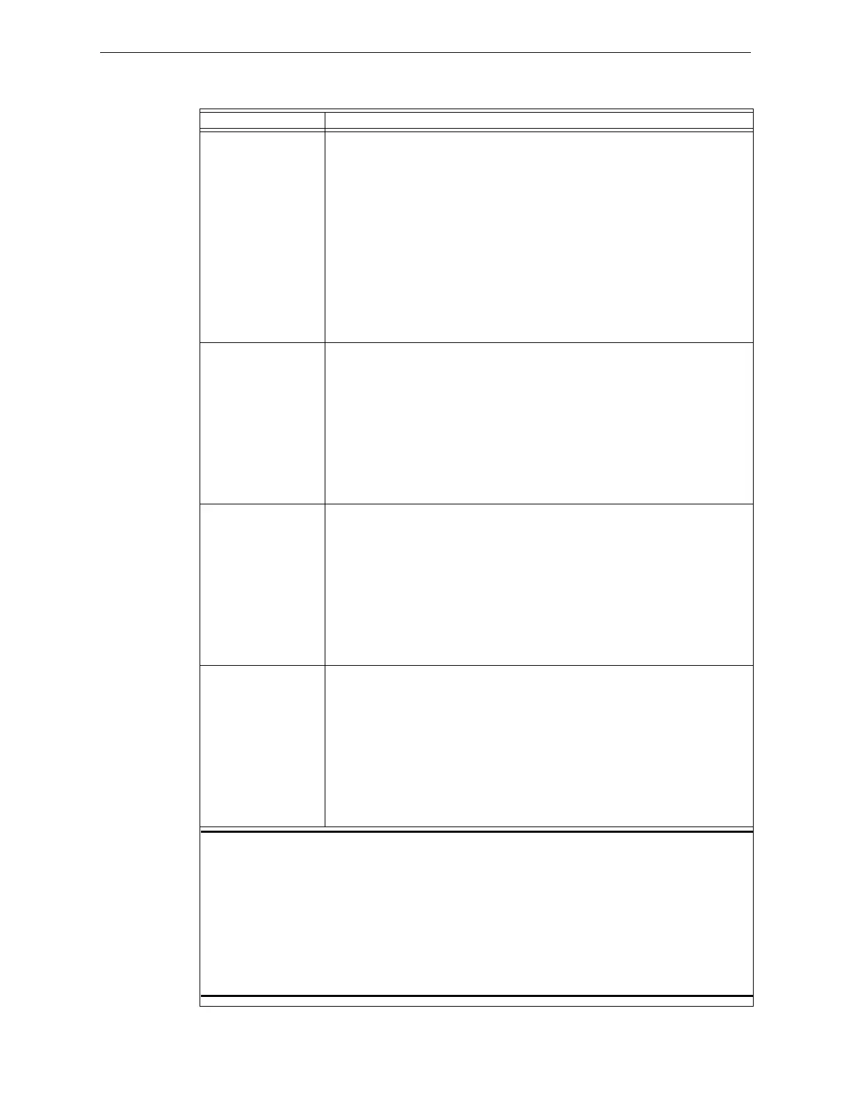
4.1.2 Expected Operations Conditions
Table 4.1.2.1 lists the conditions, response process of the condition and the expected operation.
Condition Expected Operation
Fire Alarm The following lists the expected operation for a Fire Alarm:
Alarm condition processed by Node 1 and the response process begins as
follows:
• Alarm LED Turned ON
• Alarmed Device location displayed on text display
• NAC Outputs and Municipal/Line Reversal or Releasing Output activated
• Alarm sounder activated
• Alarm event status message queued for broadcast on network
• SLC Loop output devices (max. 250 for 2 loops) begin receiving
• Activate commands on SLC Loop 1 and Loop 2 of Node 2
• Horn Relay Contacts Transfer
• If installed, the Alarm event information is transmitted via the DACT.
CO/Gas Alarm CO/Alarm condition processed by Node 1 and the response process begins
as follows:
• HAZARD LED is Turned ON
• CO/Alarmed Device location displayed on text display
• NAC Outputs and Municipal/Line Reversal or Releasing Output activated
• CO/Alarm sounder activated
• CO/Alarm event status message queued for broadcast on network
• SLC Loop output devices (max. 250 for 2 loops) begin receiving
• Activate configured outputs on SLC Loop 1, and if used, SLC Loop 2
Supervisory Supervisory condition processed by Node 1 and the response process begins
as follows:
• Supervisory LED Turned ON
• Supervisory Device location displayed on text display
• NAC Outputs and Municipal/Line Reversal or Releasing Output activated
• Supervisory sounder activated
• Supervisory event status message queued for broadcast on network
• SLC Loop output devices (max. 250 for 2 loops) begin receiving
• Activate commands on SLC Loop 1 and Loop 2 of Node 2
Trouble Trouble condition processed by Node 1 and the response process begins as
follows:
• Trouble LED Turned ON
• Trouble Device location displayed on text display
• NAC Outputs and Municipal/Line Reversal or Releasing Output activated
• Trouble sounder activated
• Trouble event status message queued for broadcast on network
• SLC Loop output devices (max. 250 for 2 loops) begin receiving
• Activate commands on SLC Loop 1 and Loop 2 of Node 2
NOTE: On the LCD-SLP Display, a CO Alarm illuminates a dedicated HAZARD LED.
- All LCD Displays provide, Node, SLC Loop, Device Address and user text description
information in the text display area.
- The sounder produces a unique Coded 4 pattern until acknowledged.
- The LCD-E3 Display flashes the word, “CO ALARM”, in the top line in response to a CO Alarm
condition in lieu of the BLUE LED. The sounder produces a coded 4 pattern until
acknowledged.
- The LCD-7100 Display flashes the word, “CO ALARM”, in the top line in response to a CO Alarm
condition in lieu of the BLUE LED. The sounder produces a March tone pattern until
acknowledged.
Table 4.1.2.1 Expected Operations Conditions

 Loading...


