18 S3 Series UL Listing Document — P/N LS10005-051GF-E:D3 3/09/2016
Installation Wiring Signaling Line Circuit (SLC) (SLC-PM/SLC95-PM)
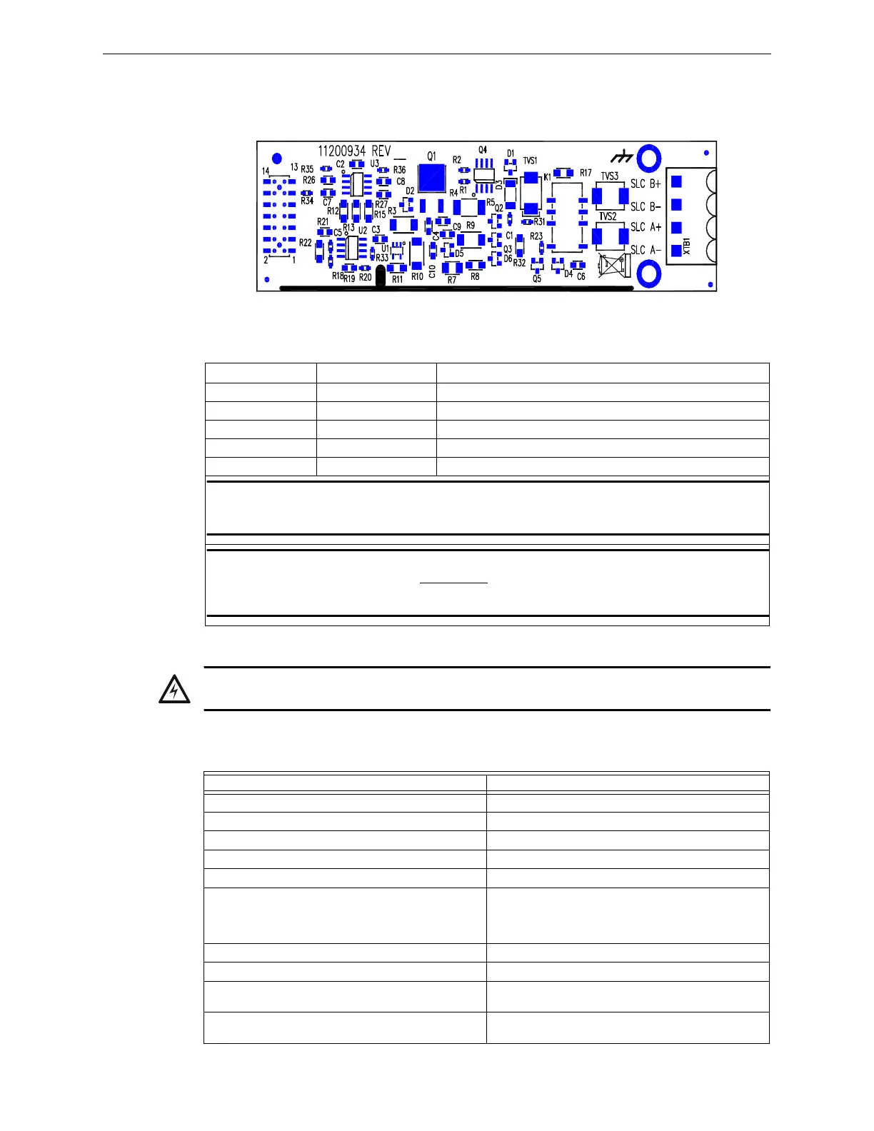
2.6.2 SLC-PM Installation Wiring Diagram- System Sensor
Figure 2.6.2.1 illustrates the SLC-PM circuit board diagram. For system assembly and installation wiring ter-
minal designations, refer to the SLC-PM/SLC95-PM Installation Instructions, P/N: LS10044-000GF-E. You
can download this document from the Gamewell-FCI Website (www.gamewell-fci.com).
Figure 2.6.2.1 SLC-PM Circuit Board
2.6.3 SLC-PM Installation Wiring Designations
Table 2.6.3.1 lists the SLC-PM installation wiring designations.
2.6.4 SLC-PM Signaling Line Circuit Specifications
Table 2.6.4.1 lists the SLC-PM signaling line circuit specifications.
2.
Designation Description Comments
TB1-1 SLC A- Style 6, Style 7 RETURN (See Note 1)
TB1-2 SLC A+ Style 6, Style 7 RETURN (See Note 1)
TB1-3 SLC B- Style 4/6, Style 7 OUT (See Note 1)
TB1-4 SLC B+ Style 4/6, Style 7 OUT (See Note 1)
J1 SLC-PM Loop 1 Connects to J5 of the SLP-E3 (See Note 2)
NOTE: For Style 4, use Terminals B+ and B- only. For Style 6, use terminals B+ and B- and
connect RETURN wiring to A+ and A-. For Style 7 (Class X), wire the same as Style 6 and use
the M500X Isolator Modules per the recommendations as required.
NOTE 2: Mount the SLC-PM board component side up. Insert the connector pins extending from
J5 on the SLP-E3 to the J1 connector underneath the SLC-PM board. (For additional information,
refer to the Warning and the SLC-PM/SLC95-PM Installation Instructions,
P/N: LS10044-000GF-E).
Table 2.6.3.1 SLC-PM Installation Wiring Designations
WARNING: SLC-PM INSTALLATION TO SLP-E3 REQUIREMENT:
INSTALL THE SLC-PM BOARD COMPONENT SIDE UP.
Requirements SLC-PM Specifications
Circuit Supervision: Supervised
Circuit Power-Limited: Class 2 Power-Limited
Nominal Voltage, Frequency: 24 VDC (from FLPS-7 power supply)
Standby Current max. voltage, rated: 0.014 amp
Alarm Current: 0.014 amp
Identify the Manufacturer’s Name, Model
designation for appliances to be used on the circuit
or reference the device compatibility
section/document.
Refer to the Compatibility Addendum to Gamewell-
FCI Manuals, P/N: 9000-0427-L8.
Max. Line Impedance: 40 Ohms and .5 µF line capacitance
Ground Fault Test Impedance: Zero Ohms
Impedance values and ground faults are
annunciated.
GND FAULT LED or LCD-SLP
Identified by class or by class/style: One Class A, Style 6, Style 7 or Class B, Style 4
signaling line circuit.
Table 2.6.4.1 SLC-PM Signaling Line Circuit Specifications

 Loading...


