14 S3 Series UL Listing Document — P/N LS10005-051GF-E:D3 3/09/2016
Installation Wiring SLP-E3 Main Circuit Installation Wiring Diagram
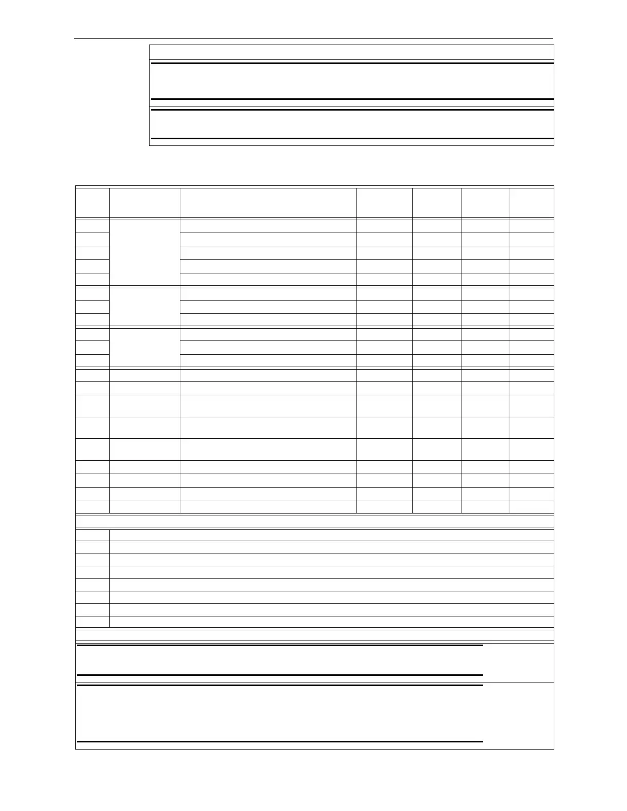
2.2.5 SLP-E3 Standby Battery Calculation Chart
Table 2.2.5.1 lists the SLP-E3 Standby Battery Calculations.
NOTES
NOTE 1: Four hour standby permitted for installations with automatic backup generators. 24, 60
hours as required by code. Use Table 2.2.5.1 to obtain the correct sized battery capacity
required.
NOTE 2: 5, 15, 30 or 60 minute Alarm duration as required by code. Use Table 2.2.5.1 to obtain
the correct sized battery capacity required.
Table 2.2.4.1 SLP-E3 Main Circuit Specifications
Qty Module Description
Supv.
Current
Alarm
Current
Total
Supv.
Current
Total
Alarm
Current
SLP-E3 Smart Loop Panel-Main Board 0.100 A 0.180 A
Resettable Auxiliary Power, max. 1.75 A
Non-Resettable Auxiliary Power, max. 1.75 A
Municipal, max. 0.75 A
Notification Appliances (See Note 6)
SLC-PM Signaling Line Circuit - Personality Board 0.014 A 0.014 A
Addressable Sensors & Modules (See Note 6)
Signaling Line Circuits (SLCs) (See Note 6)
SLC95-PM Signaling Line Circuit 95 - Personality Board 0.016 A 0.016 A
Addressable Sensors & Modules (See Note 6)
Signaling Line Circuits (SLCs) (See Note 6)
LCD-SLP LCD Display/Switch Control (See Note 3) 0.030 A 0.065 A
LCD-E3 LCD Display/Switch Control 0.024 A 0.028 A
ASM-16 Annunciator Switch Module 0.011 amp (with
no LEDs lit)
0.011 amp
(See Note 4)
ANU-48 Remote LED Driver Assembly 0.011 amp 0.011 amp
(See Note 5)
LCD-7100/
RAN-7100
Remote Display Module 0.12 A 0.23 A
DACT-E3 Digital Dialer Communication Transmitter 0.018 A 0.018 A
RPT-E3-UTP ARCNet Repeater 0.016 A 0.017 A
FML-E3 Fiber-Optic Multi-Mode Board 0.053 A 0.053 A
FSL-E3 Fiber-Optic Single Mode Board 0.079 A 0.079 A
User Calculation Totals
A Total Supervisory Current (See Note 6)
B Enter number of standby hours required (See Note 1)
C Multiply Line A times hours in Line B—enter
D Total alarm current from above
E Enter alarm sounding period in hours.
F Multiply Line D times Line E –enter
G Total of Lines C & F—enter
H Multiply Line G by 1.2 --- enter (Total ampere/hours required) (See Note 2)
NOTES
NOTE 1: 24 hours for NFPA 72 protected premises or Central Station signaling, or Auxiliary, or Remote Supervising
Station Fire Alarm Systems.
NOTE 2: Use the next size battery with a capacity greater than required. (Use only Gamewell-FCI Models: B-17R,
B-55R, BAT-12120, BAT-12260, or BAT-12550 batteries). The maximum standby current is 0.560 A for 60 hours
when using 55 A/H batteries.
To comply with FM standards, use 0.247 A for 90 hours when using 55 A/H batteries.
The system batteries must be replaced as a set.
Table 2.2.5.1 SLP-E3 Standby Battery Calculation Chart

 Loading...


