S3 Series UL Listing Document — P/N LS10005-051GF-E:D3 3/09/2016 37
S3 Series System, B-Size Cabinet Assembly Installation Wiring
2.16 S3 Series System, B-Size Cabinet Assembly
The S3 Series, B-Size cabinet assembly (Part Number: E3BB-BB/RB) typically houses the following units:
• Backbox
• Inner Door
• Outer Door
– Door Insert
• Hardware Kit
2.16.1 S3 Series, B-Size Cabinet Installation
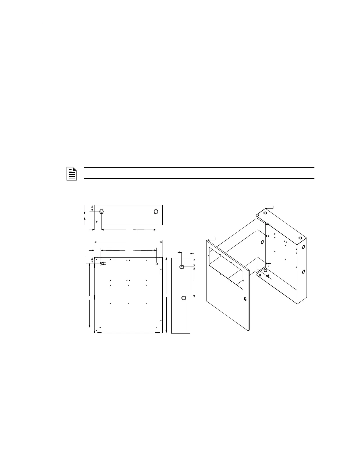
Figure 2.16.1.1 illustrates the S3 Series, B-Size cabinet dimensions.
Figure 2.16.1.2 illustrates the S3 Series, B-Size cabinet outer door and backbox installation. For installation
instructions, refer to the following:
1. To mount the outer door to the backbox, insert four, #6 nuts in the four-hole mounting pattern and secure
the nuts from the outer door to the left side of the backbox as shown in Locations 1, 2, 3 and 4 of
Figure 2.16.1.2.
– SLP Main Board – FLPS-7 Power Supply – RPT-E3-UTP (Optional)
– SLC-PM/SLC95-PM – Batteries – DACT-E3 (Optional)
–LCD-SLP Display Panel – ASM-16 (Optional)
– ANU-48 (Optional) – LCD-E3 (Optional)
NOTE: Use the Hardware Kit provided with the S3 Series, B-Size Cabinet assembly.
Figure 2.16.1.1 S3 Series, B-Size Cabinet
Dimensions
Figure 2.16.1.2 S3 Series Cabinet B,
Outer Door to Backbox Installation
16.00"
19.38"
16.69"
BACKBOX TOP
BACKBOX
SIDE PANEL
BACKBOX
19 3/8"
1.50"
16.38"
1.25"
8.00"
1.50"
BACKBOX DEPTH = 4.50"
1.35"
1
2
34
.25"
.50"
3.38"
2.25"
4.50"
CABINET B,
OUTER DOOR
1
2
3
4
CABINET B,
BACKBOX
N
U
T
,
#
6
,
H
E
X
4
P
L
A
C
E
S

 Loading...


