22 S3 Series UL Listing Document — P/N LS10005-051GF-E:D3 3/09/2016
Installation Wiring Remote Annunciator/Keypad Circuits
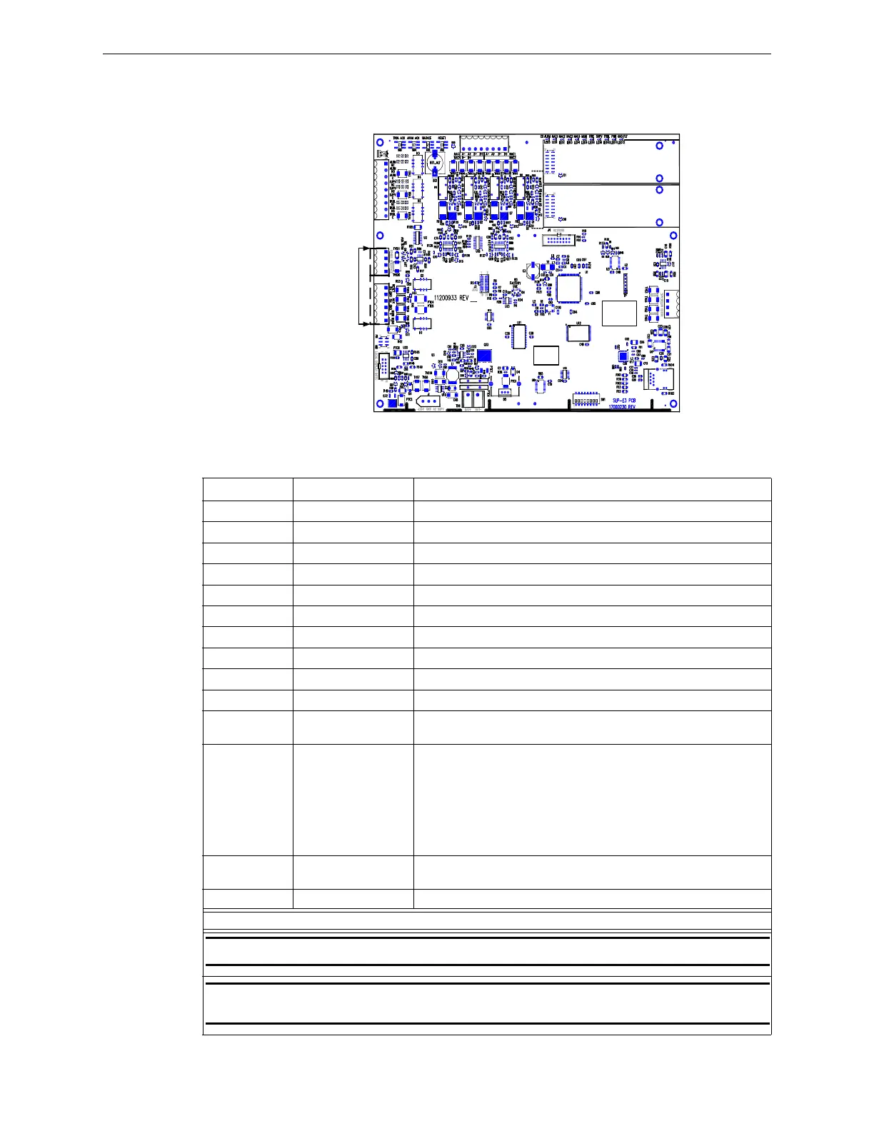
2.7.10 LCD-SLP Installation Wiring Diagram
Figure 2.7.10.1 illustrates the LCD-SLP circuit board diagram. For system assembly and installation wiring
terminal designations, refer to the LCD-SLP Installation Instructions, P/N: LS10045-000GF-E. You can
download this document from the Gamewell-FCI Website (www.gamewell-fci.com).
Figure 2.7.10.1 LCD-SLP Circuit Board Diagram
2.7.11 LCD-SLP Installation Wiring Terminals
Table 2.7.11.1 lists the LCD-SLP installation wiring designations.
SLP-E3
SLC-PM/SLC95-PM #2
SLC-PM/SLC95-PM #1
TB4
TB3
TB2
TB1
TB5
BAR CODE
LABEL
PRODUCT
SERIAL NUMBER
PRODUCT
DATE CODE
LABEL
ETHERNET
J2
REMOTE
ANNUNCIATORS
W1
J7
B- B+
J1
J5
J6
J1
Designation Description Comments
TB1-1 RS-485A Communications IN (See Notes 1 & 2)
TB1-2 RS-485B Communications IN (See Notes 1 & 2)
TB1-3 RS-485A Communications OUT (See Note 2)
TB1-4 RS-485B Communications OUT (See Note 2)
TB2-1 +24 V +24 V non-resettable power IN (See Notes 1 & 2)
TB2-2 GND IN GROUND IN (See Notes 1 & 2)
TB2-3 +24 V OUT +24 V non-resettable power OUT (See Note 2)
TB2-4 GND OUT GROUND OUT (See Note 2)
TB2-5 GND Extra Ground
TB2-6 Earth Ground Earth Ground
J5 Local Connection RS-485 communications and power (ribbon cable local only)
(See Note 3).
J6 Keypad Lock Jumper or Keyswitch:
1. To use the Jumper, do either of the following:
JMP IN = Disabled
JMP OUT = Enabled
OR
2. To use the keyswitch, connect the PK-625 keyswitch.
This keyswitch is keyed alike with the door lock, and must be
operated to activate the keypad.
W1 RS-485 Termination W1 should be ON (top 2 pins), if it is the first or last device on the
RS-485 bus. Otherwise, W1 should be OFF (bottom 2 pins).
SW1 Display Address Binary Switch Addressing (See Note 4)
NOTES
NOTE 1: If you do not use J5, these connections are required.
NOTE 2: Use this connection only in remote installations. Do not use this connection when the
LCD-SLP is mounted in the same cabinet with the SLP-E3.
Table 2.7.11.1 LCD-SLP Installation Wiring Terminals

 Loading...


