S3 Series UL Listing Document — P/N LS10005-051GF-E:D3 3/09/2016 29
Communication Circuits Installation Wiring
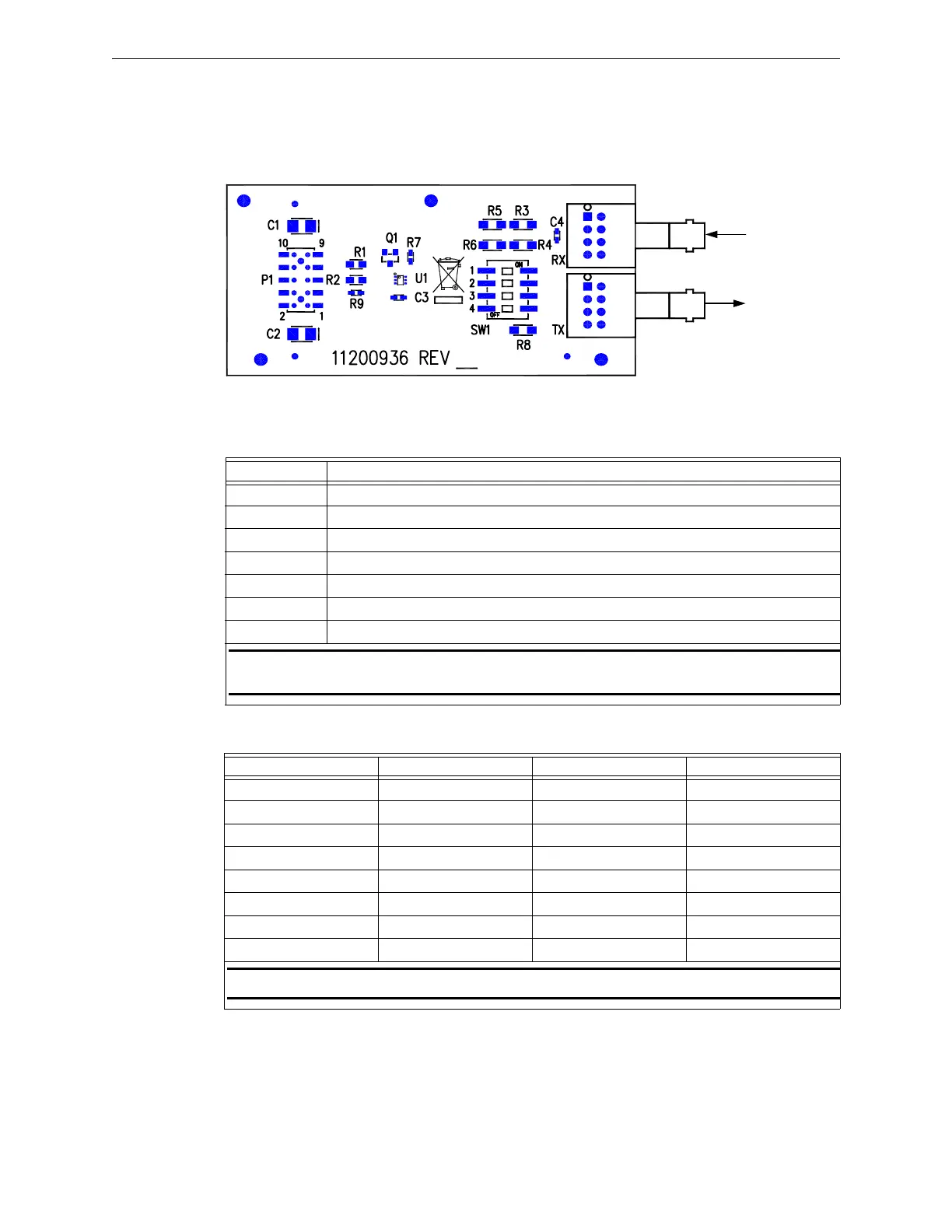
2.10.6 FML-E3 Installation Wiring Diagram
The Fiber-Optic Multi-Mode (FML-E3) is an optional module that provides fiber connectivity to the network.
One FML-E3 is used per a network channel to transmit/receive. Figure 2.10.6.1 illustrates the FML-E3 circuit
board diagram. For system assembly and installation wiring terminal designations, refer to the FML-E3/FSL-
E3 Installation Instructions, P/N: LS10046-000GF-E. You can download this document from the Gamewell-
FCI Website (www.gamewell-fci.com).
Figure 2.10.6.1 FML-E3 Circuit Board Diagram
2.10.7 FML-E3 Installation Wiring Terminals
Table 2.10.7.1 lists the FML-E3 installation wiring terminals.
Table 2.10.7.2 lists the FML-E3 switch settings and drive currents.
FML-E3
J2
J1
FIBER-IN
FIBER-OUT
Designation Description
J1 Connects to the transmitting fiber. (See Note 1)
J2 Connect to the receiving fiber. (See Note 1)
SW1-1
Sets the optical output power for the transmitting fiber. (See Table 2.10.7.2)
SW1-2
Sets the optical output power for the transmitting fiber. (See Table 2.10.7.2)
SW1-3
Sets the optical output power for the transmitting fiber. (See Table 2.10.7.2)
SW1-4
Not used
P1 Plugs on to J5 (Port 1) or J6 (Port 2) of the RPT-E3-UTP.
NOTE: Use standard ST connector fiber-optic cable, multi-mode, up to 200 µ (optimized for
62.5/125 µ). Signal loss up to 8dB maximum between nodes.
Table 2.10.7.1 FML-E3 Installation Wiring Terminals
SW1-1 SW1-2 SW1-3 Drive Current
OFF OFF OFF 10 mA
OFF OFF ON 20 mA
OFF ON OFF 32 mA
OFF ON ON 42 mA
ON OFF OFF 54 mA
ON OFF ON 64 mA
ON ON OFF 76 mA
ON ON ON 86 mA
NOTE: SW1-4 is not used.
Table 2.10.7.2 FML-E3 Switch Settings and Drive Currents

 Loading...


