36 S3 Series UL Listing Document — P/N LS10005-051GF-E:D3 3/09/2016
Installation Wiring Separation of Circuits
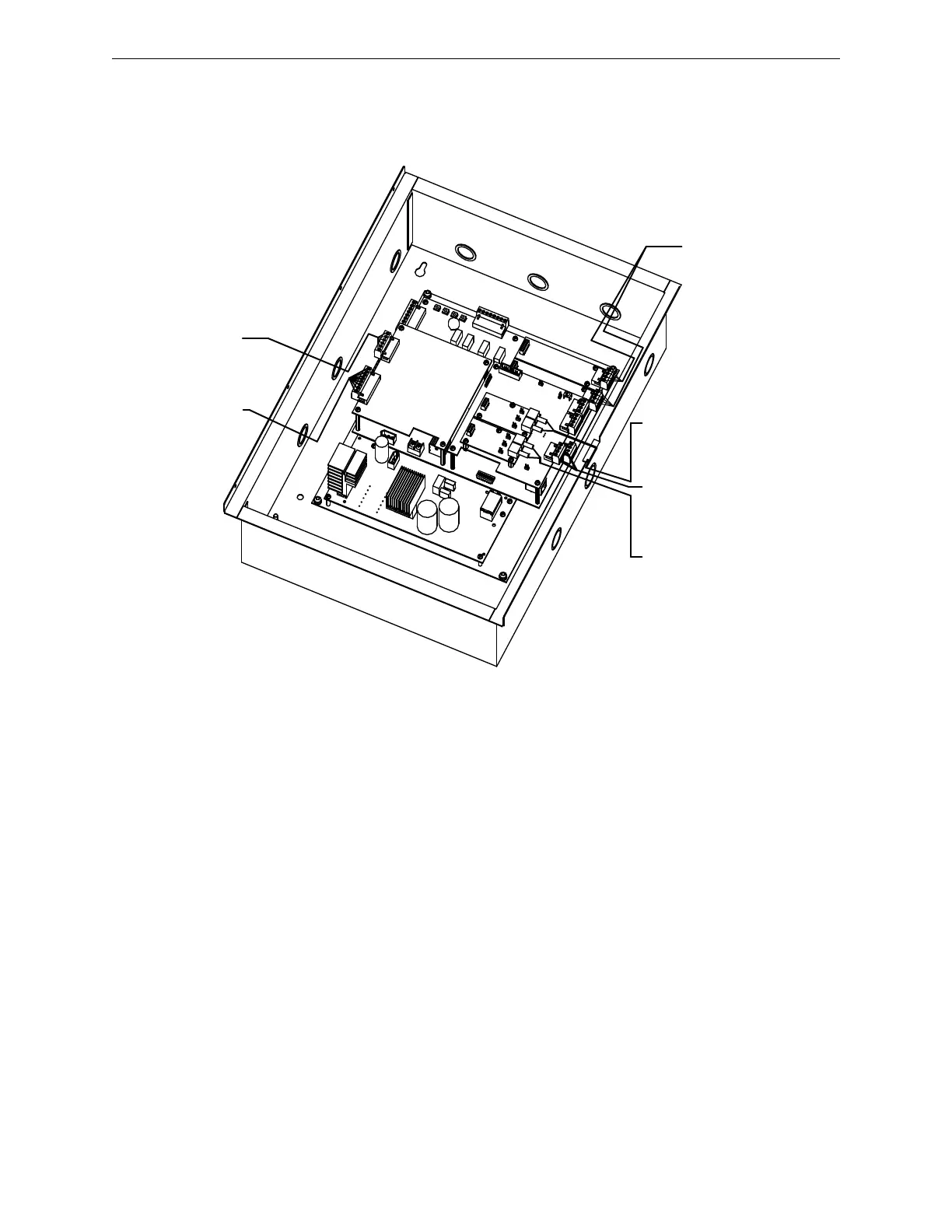
Figure 2.15.1.2 illustrates the S3 Series System unit, Class 2 power-limited and non-power-limited wiring
extending from the SLP-E3 and FLPS-7 modules.
Figure 2.15.1.2 S3 Series, SLP-BB Cabinet, Class 2 Power-Limited and Non-Power-
Limited Wiring
(Optional Top Level Circuit Board Configuration)
D
A
C
T
-
E
3
R
P
T
-
E
3
-
U
T
P
F
S
L
-
E
3
#
1
S
L
P
-
E
3
T
B
1
T
B
2
T
B
1
T
B
1
F
L
P
S
-
7
J
2
J
1
J
2
J
1
F
S
L
-
E
3
#
2
S
L
C
-
P
M
#
2
SLC CIRCUITS
FROM SLC-PM
(SYSTEM SENSOR) OR
SLC95-PM (APOLLO) TB1
(CLASS 2 POWER-LIMITED,
SUPERVISED)
-CONNECT TO PRINTER
PORT.
T
B
1
S
L
C
-
P
M
#
1
AUXILIARY RS485
FROM DACT-E3 TB2
(CLASS 2
POWER-LIMITED)
TELEPHONE LINES
FROM DACT-E3 TB2
(CLASS 2
NON POWER-LIMITED)
NETWORK
USING FIBER
FROM FSL-E3 #2 J17 J2
(CLASS 2 POWER-LIMITED)
NETWORK
USING FIBER
FROM FSL-E3 #1 J2 & J1
(CLASS 2 POWER-LIMITED)
NETWORK
USING WIRE
FROM RPT-E3-UTP TB1
(CLASS 2 POWER-LIMITED)

 Loading...


