42 S3 Series UL Listing Document — P/N LS10005-051GF-E:D3 3/09/2016
Installation Wiring E3BB-FLUSH-LCD Cabinet A2 Assembly
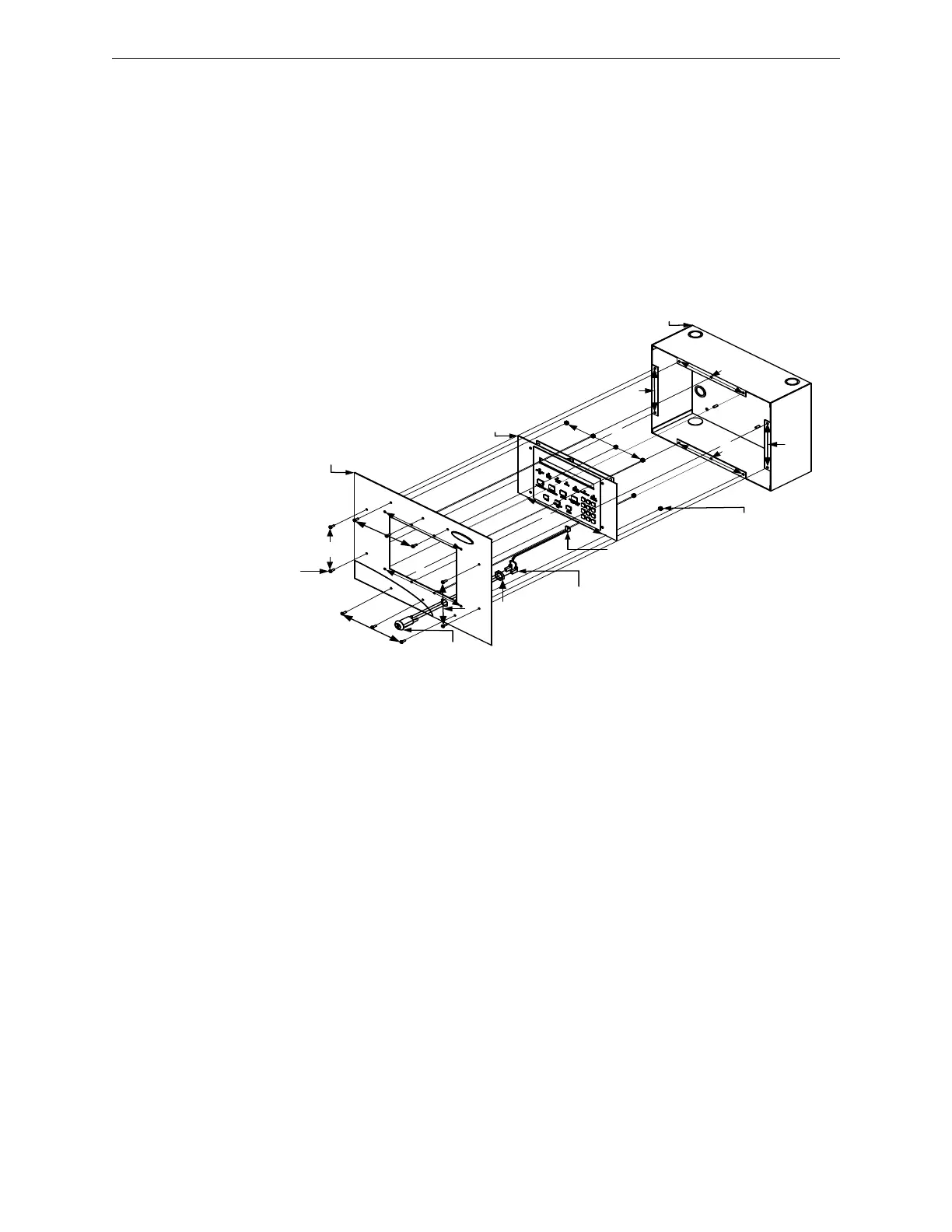
2.19.1.1 E3BB-FLUSH-LCD Cabinet A2 Front Cover to Backbox Installation
Figure 2.19.1.1.1 illustrates the E3BB-FLUSH-LCD front cover to the backbox installation.
1. Mount the keyswitch to the E3BB-FLUSH-LCD Flush Mount Front Cover and secure with one, nut (3/4-
24 THD Hex) as shown in Location 1 in the figure below.
2. Attach the keyswitch cable to the key as shown in Location 2 in the figure below.
3. To mount the LCD-SLP keypad to the E3BB-FLUSH-LCD Flush Mount Front Cover, insert eight nuts
(#6-32, Hex Keps) in the eight-hole mounting pattern and secure the nuts from the keypad to the front
cover as shown in Location 3 in the figure below.
4. Plug-in the P2 keyswitch cable to the W2 terminal on the LCD-SLP display as shown in Location 4 in the
figure below.
5. Attach the E3BB-FLUSH-LCD Flush Mount Front Cover to the backbox.
6. Insert eight screws (#6-32 x 3/8” PHBHD, BLK) in the eight-hole mounting pattern and secure the
screws from the front cover to the backbox as shown in Location 5 in the figure below.
.
Figure 2.19.1.1.1 E3BB-FLUSH-LCD Cabinet A2 Installation
LCD-SLP/
LCD-E3
1
2
4
1
P2, KEYSWITCH
CABLE (2 IN RT.
ANGLE HEADER)
NUT, (#6-32) HEX
KEPS (8 PLACES)
KEYSWITCH
CABLE
BACKBOX
E3BB-FLUSH-LCD
FLUSH MOUNT
FRONT COVER
KEYSWITCH
NUT,
¾”-24
THD HEX
SCREW,
(#6-32 x 3/8")
BHBHD, BLK
(8 PLACES)
5
5
5
5 3
3
3
3
5
5
5
5

 Loading...


