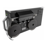
2.5 Analyzer Modules
The Vertex M system is populated with one or more types of analyzer modules. Each system
may contain Chemcassette™ modules or Pyrolyzer modules. Modules are installed in slots.
Tier 1
CC CC
CC
PYRO
Slot 1 Slot 2 Slot 3
Table 2-1. Module Tier Structure
Chemcassette™ modules occupy one slot each. However, Pyrolyzer Chemcassette™ modules are
to be installed in slots 1 and 2. Pyrolyzer configuration and status information will appear in
slot 2.
Number of
Points
Installed into
Slots
Total Possible per Vertex M sys-
tem
Chemcassette™ 8 1, 2 or 3 3
Pyrolizer 8 1 and 2 only 1
Table 2-2. Required Slots
Examples of possible combinations in a Vertex M system:
l
One, Two or Three Chemcassette™ modules
l
One pyrolyzer Chemcassette™ module
l
One pyrolyzer Chemcassette™ module, one Chemcassette™ module
The monitor will include only those modules specified at time of ordering.
2.6 Sampling System
Each Analyzer module is a monitoring center for sampling lines from sample locations. As they
apply to the Vertex M system, the words point, line and location require definition:
l
A location is a place to be monitored
l
Sample atmosphere runs from the location to the Vertex M system via a line
l
Each of the 24 sample tubing connections on the Vertex M system corresponds to a point. A
sample line can be connected directly to a single point or multiple points via a 4-port
manifold (PN: 1295-0349)
The system draws air simultaneously from all locations. Two different types of flow are:
l
Transport flow: high-velocity, large-volume air movement through the lines
l
Sample flow: air admitted to the Chemcassette™ detection system
Vertex M 25 User Manual
 Loading...
