4 Assembly
Linear actuators MC100 • MC103
Operating Manual Version 2.1 - March 2011 21
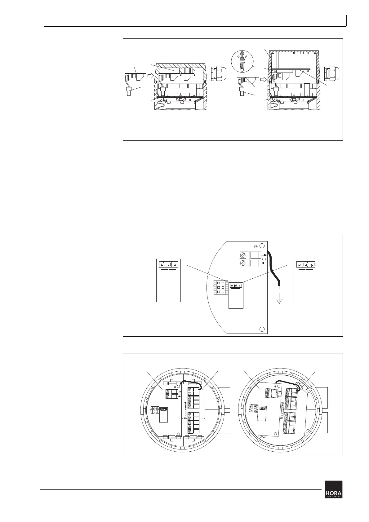
3 Push the female plug of the (115) PCB for the mA output signal onto the pin strip
(123) of the main PCB (110) . In the process pay attention to the notches on the
socket board and female plug.
4 Attach the single cable from the PCB (111) for the mA output signal to terminal X
of the push-fit PCB (107).
5 Use the jumper to select the signal range for the output signal:
• Jumper right: 4 … 20 mA
• Jumper left: 0 … 20 mA
27 Spacers
111 PCB for mA output signal
107 Push-fit PCB for 24 V or 230 V
115 Female plug
110 Main board
201 Cover for 24 V or 230 V*
diagram 13 Fitting a PCB for the mA output signal
230 V
24 V
201
110
111
115
27
107
115
111
110
201
201
27
111
115
110
107
201
111
115
110
24 V 230 V
diagram 14 Setting the PCB for the mA output signal
diagram 15 Connecting the PCB for the mA output signal to
the push-fit PCB
4 ... 20 mA0 ... 20 mA
0..20 mA
4..20 mA
0..20 mA
4..20 mA
0..20 mA
4..20 mA
X
N2
0..20 mA
4..20 mA
X
N2
0..20 mA
4..20 mA
X
N2
X
X