Chapter 2 Operating Your Universal Counter
Using the Gate & External Arm Menu Key
2-22 Operating Guide
2
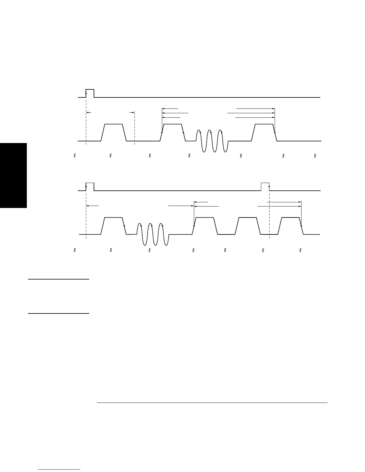
Figure 2-3. HP 53132A (With S/N Prefix 3646 and Above) External Arming
NOTE
The examples in Figure 2-3 have the input signal applied to Channel 1
with COMMON 1: ON, Channel 1 SLOPE: POS, and Channel 2
SLOPE: NEG. Thus, the signals applied to Channel 1 and Channel 2 are
identical, however, the channel events occur on opposite slopes.
DESIRED T.I. MEASUREMENT
START STOP
ACTUAL T.I. MEAS
START: EXT, SLOPE: POS, DELAY: TIME, T: (specified), STOP : AUTO, DELAY : EVENT, E : 5
DELAY STOP TO 4th EVENT
234 5
START DELAY TIME
EXT ARM INPUT
DESIRED T.I. MEASUREMENT
START STOP
ACTUAL T.I. MEAS
23 4
DELAY START BY 4 CHAN 2 EVENTS
EXT ARM INPUT
1
5
START: EXT, SLOPE: POS, DELAY: EVENT, E: 5, STOP : EXT, SLOPE : NEG, DELAY : NONE
1

 Loading...


