18
Step Command Remarks
7. Enter interface view of the
interface that connects to the
internal network.
interface
interface-type
interface-number
The following interface types are
supported:
• Layer 3 Ethernet interfaces.
• Layer 3 Ethernet subinterfaces.
8. Enable the ARP PnP feature.
arp pnp
By default, the ARP PnP feature is
disabled.
Displaying and maintaining ARP PnP
Execute display commands in any view.
Task Command
Display ARP PnP mappings.
display arp pnp
[
interface
interface-type interface-number ]
ARP PnP configuration example
Network requirements
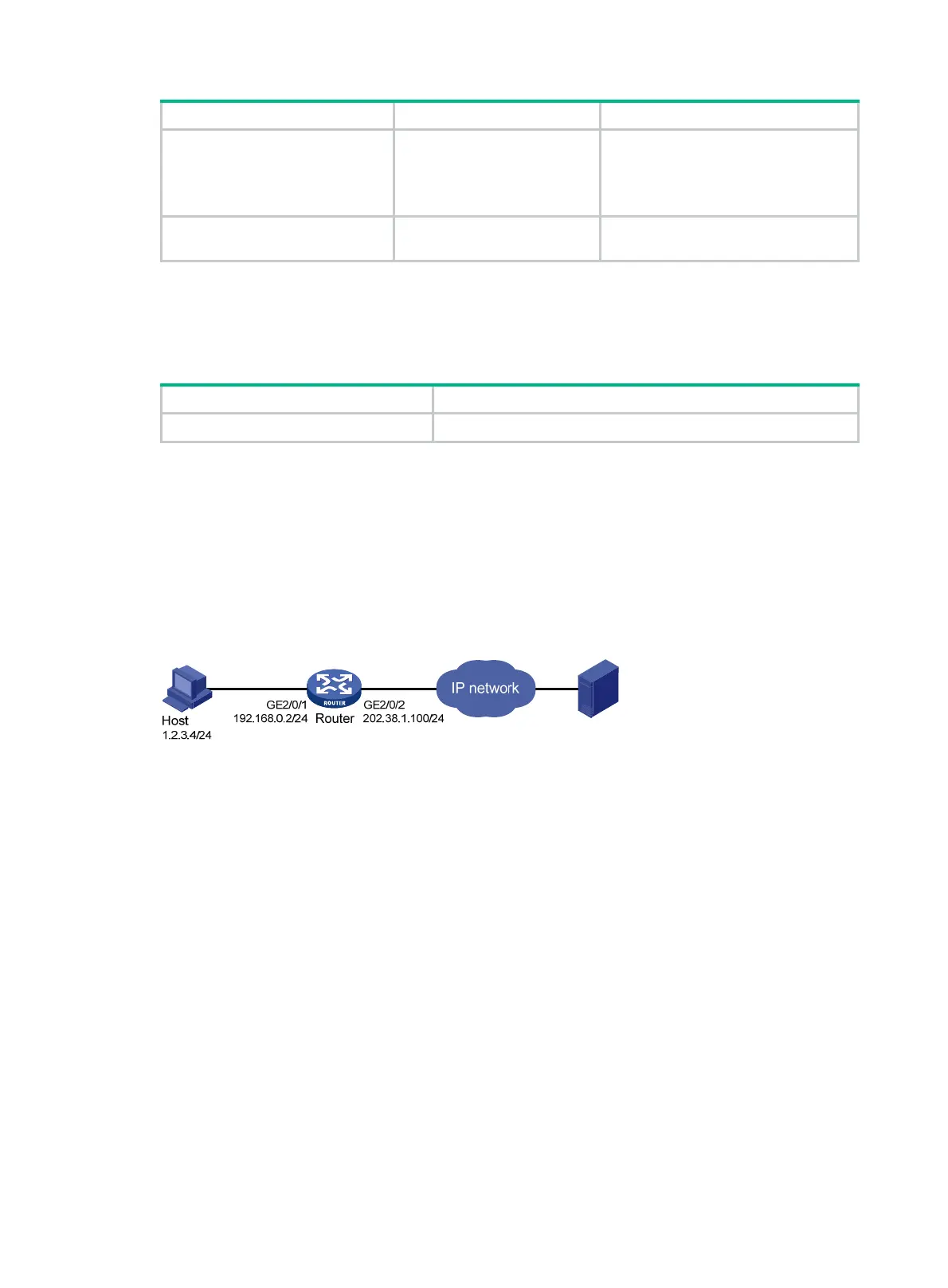
As shown in Figure 7, configure the ARP PnP feature to allow the host at 1.2.3.4 to access the
external server through GigabitEthernet 2/0/1.
Figure 7 Network diagram
Configuration procedure
1. Configure NAT:
# Specify IP addresses for GigabitEthernet 2/0/1 and GigabitEthernet 2/0/2.
<Router> system-view
[Router] interface gigabitethernet 2/0/1
[Router-GigabitEthernet2/0/1] ip address 192.168.0.2 24
[Router-GigabitEthernet2/0/1] quit
[Router] interface gigabitethernet 2/0/2
[Router-GigabitEthernet2/0/2] ip address 202.38.1.100 24
[Router-GigabitEthernet2/0/2] quit
# Configure ACL 2000 to identify packets from subnet 192.168.0.0/24.
[Router] acl number 2000
[Router-acl-basic-2000] rule permit source 192.168.0.0 0.0.0.255
[Router-acl-basic-2000] quit
# Create address group 1, and add address 202.38.1.100 to the group.
[Router] nat address-group 1
[Router-nat-address-group-1] address 202.38.1.100 202.38.1.100