357
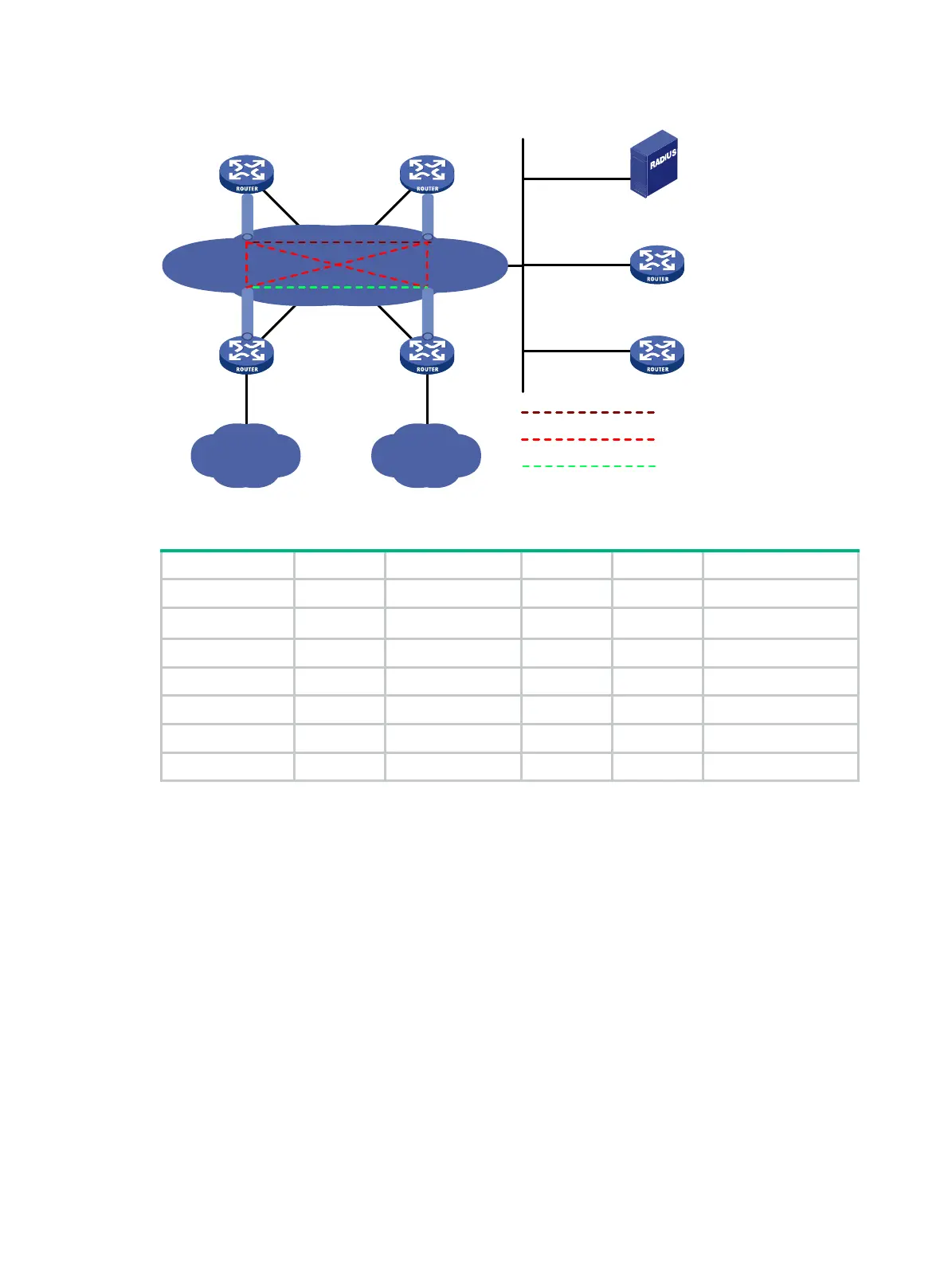
Figure 147 Network diagram
Table 13 Interface and IP address assignment
Device Interface IP address Device Interface IP address
Hub 1 GE2/0/1 1::1/64 Spoke 1 GE2/0/1 1::3/64
Tunnel1 192:168::1/64
GE2/0/2 192:168:1::1/64
Hub 2 GE2/0/1 1::2/64 Tunnel1 192:168::3/64
Tunnel1 192:168::2/64 Spoke 2 GE2/0/1 1::4/64
AAA server 1::10/64 GE2/0/2 192:168:2::1/64
Primary server GE2/0/1 1::11/64 Tunnel1 192:168::4/64
Secondary server GE2/0/1 1::12/64
Configuring the primary VAM server
1. Configure IP addresses for the interfaces. (Details not shown.)
2. Configure AAA:
# Configure RADIUS scheme abc.
<PrimaryServer> system-view
[PrimaryServer] radius scheme abc
[PrimaryServer-radius-abc] primary authentication ipv6 1::10 1812
[PrimaryServer-radius-abc] primary accounting ipv6 1::10 1813
[PrimaryServer-radius-abc] key authentication simple 123
[PrimaryServer-radius-abc] key accounting simple 123
[PrimaryServer-radius-abc] user-name-format without-domain
[PrimaryServer-radius-abc] quit
[PrimaryServer] radius session-control enable
# Configure AAA methods for ISP domain abc.
[PrimaryServer] domain abc
[PrimaryServer-isp-abc] authentication advpn radius-scheme abc
IP network
Spoke1
Spoke2
Site 1
Site 2
Hub1 Hub2
Tunnel1
Tunnel1
Tunnel1 Tunnel1
Primary server
Secondary server
AAA server
GE2/0/1
GE2/0/1
GE2/0/1
GE2/0/1
GE2/0/1
GE2/0/1
GE2/0/2 GE2/0/2
Hub-to-Hub static tunnel
Hub-to-Spoke static tunnel
Spoke-to-Spoke dynamic tunnel