1 2 1
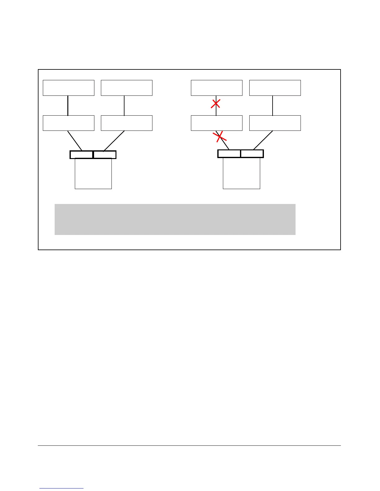
DC Switch 1 DC Switch 2
Blade Switch 1 Blade Switch 2
Server
Uplink Ports
Uplink Ports
NIC 1 NIC 2
3 4
2
DC Switch 1
Blade Switch 1
3
Downlink Ports
Downlink Ports
DC Switch 2
Blade Switch 2
Server
4
NIC 1 NIC 2
Links 1 and 3 represent the primary path from the NIC team to the DC switch. Whenthe uplink (link 3)
between Blade Switch 1 and DC Switch 1 fails, the UFD feature will disconnect the link between NIC team
member 1 and Blade Switch 1 (link 1). The NIC team will fail over to the redundant path from NIC team
member 2 through to DC Switch 2.
Figure 10-24. Representation of an UFD Configuration
Guidelines
The following lists guidelines for UFD. These guidelines are applicable to
blade switches only when there is a clear difference between downlink and
uplink ports.
■ A link to monitor (LtM) can be one or more uplink ports
■ A link to disable (LtD) can be one or more downlink ports
■ An LtM or LtD can be a trunk port
■ A trunk port must be configured before designating it as a link to monitor
or a link to disable
■ Ports already configured as LtM or LtD cannot be deleted. An Inter-Switch
Link (ISL) can be an LtM, but not an LtD.
■ NIC teaming must be active-standby (Network Fault Tolerance or other)
■ There is a physical limit of 9 LtM ports; the ISL can function as an LtM port
10-39

 Loading...


