9.10 Appendix
This section describes the procedure for adding an easy power receptacle (pressfit type)
connector.This section describes the procedure for adding OT terminals.This section describes
the procedure for adding OT terminals to the surge protection box side of the power cable for
the AC surge protection box.
9.10.1 Adding OT Terminals to the Power Cable Connected to the AC Surge Protection Box
This section describes the procedure for adding OT terminals to the power cable connected to
the AC surge protection box.
9.10.2 Installing a Ground Clip
This section describes how to install a ground clip on a fast Ethernet or gigabit Ethernet (FE/
GE) cable.
9.10.1 Adding OT Terminals to the Power Cable Connected to the
AC Surge Protection Box
This section describes the procedure for adding OT terminals to the power cable connected to
the AC surge protection box.
Context
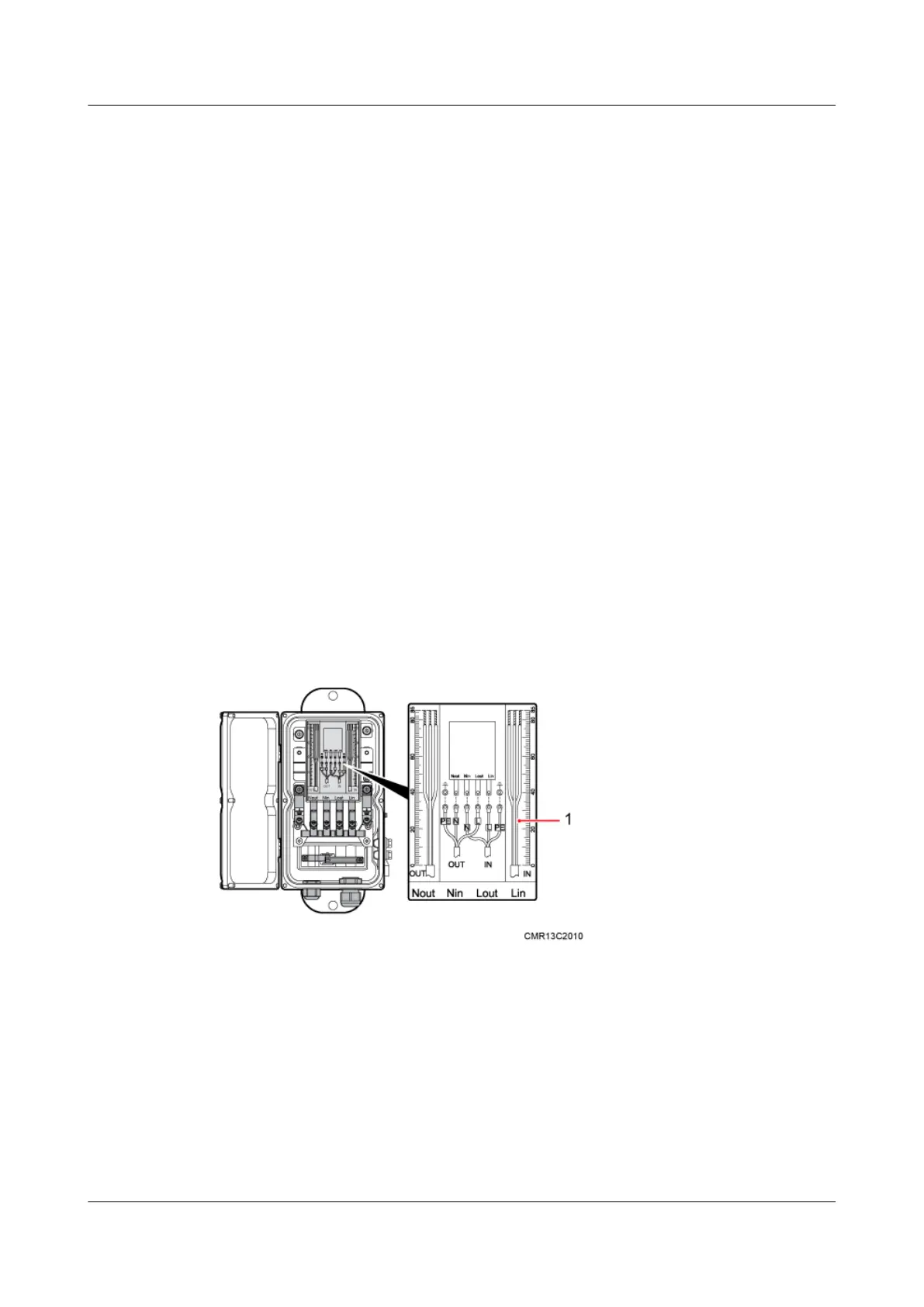
Figure 9-27 shows the cable diagram on labels.
Figure 9-27 Cable diagram on labels
(1) Cable diagram on labels
Procedure
Step 1 Cut the cable to the required length based on the actual cable route.
Step 2 If the power cable is longer than or equal to 5 m (16.4 ft.), cut the corrugated pipe into multiple
5-meter-long pieces; if the cable is shorter than 5 m (16.4 ft.), cut the corrugated pipe based on
the actual length of the power cable.
9 Installing Cables
BTS3902E WCDMA
Installation Guide
9-28 Huawei Proprietary and Confidential
Copyright © Huawei Technologies Co., Ltd.
Issue Draft A (2011-06-30)