Home
Huawei
Accessories
BTS3902E WCDMA
Huawei BTS3902E WCDMA User Manual
4
of 1
of 1 rating
113 pages
Give review
Manual
Specs
To Next Page
To Next Page
To Previous Page
To Previous Page
Loading...
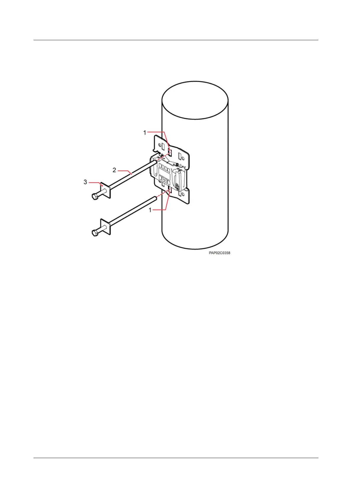
Figure 7-18
Securing the securing pieces
(1) Mounting hole group C
(2) Bolt
(3) Spacer
Step 4
Tighten the nuts to 80 N·m (708.06 lbf·in.), as shown in
Figure 7-19
.
7 Installing a BTS3902E
BTS3902E WCDMA
Installation Guide
7-16
Huawei Proprietary and Confidential
Copyright © Huawei Technologies Co., Ltd.
Issue Draft A (2011-06-30)
57
59
Table of Contents
About this Document
5
Table of Contents
9
1 Changes in the BTS3902E WCDMA Installation Guide
17
2 Installation Preparations
19
Tools and Instruments
20
Skills and Requirements for Onsite Personnel
21
3 Information about the Installation
23
BTS3902E Exterior
24
Figure 3-2 Dimensions of a BTS3902E Without a Housing
24
BTS3902E Ports
25
Figure 3-3 Dimensions of a BTS3902E with a Housing and Antennas
25
Figure 3-4 Positions of the BTS3902E Ports and Indicators
26
Table 3-1 BTS3902E Ports and Indicators
26
BTS3902E Indicators
27
Table 3-2 BTS3902E Indicators
27
BTS3902E Installation Options
28
Figure 3-5 Diameter of a Pole
29
Figure 3-6 BTS3902E Installed on a Pole
29
Figure 3-7 Diameter of a Pole
29
Figure 3-8 BTS3902E Installed on a Pole
30
Installation Clearance Requirements
31
Figure 3-9 BTS3902E Installed on a Wall
31
Figure 3-10 BTS3902E Installed on a Wood Pole
31
Figure 3-11 Recommended Installation Clearance for a Single BTS3902E
32
Figure 3-12 Minimum Installation Clearance for a Single BTS3902E
32
Figure 3-13 Recommended Installation Clearance for Two Bts3902Es Installed Side by Side
33
Figure 3-14 Minimum Installation Clearance for Two Bts3902Es Installed Side by Side
33
Figure 3-15 Recommended Installation Clearance for Two Bts3902Es Installed in a Vertical Line
34
Figure 3-16 Minimum Installation Clearance for Two Bts3902Es Installed in a Vertical Line
35
4 Unpacking the Equipment
37
5 Obtaining the ESN
39
Figure 5-1 Obtaining the ESN
40
6 Installation Process
41
Figure 6-1 Process of Installing the BTS3902E
42
7 Installing a BTS3902E
43
Mounting Kits for Installing a BTS3902E
44
Figure 7-1 Rear of a BTS3902E
44
Figure 7-2 Mounting Bracket Assembly for Installing a BTS3902E
44
Installing a BTS3902E on a Pole with the Diameter of 60 MM to 114 MM (2.36 In. to 4.49 In.)
45
Figure 7-3 Adapting Plate Assembly for Installing a BTS3902E
45
Figure 7-4 Installing the Bracket Assembly
46
Figure 7-5 Securing the Bracket Assembly Onto the Pole
46
Installing a BTS3902E on a Pole with the Diameter of 114 MM to 400 MM (4.49 In. to 15.75 In.)
47
Figure 7-6 Installing the BTS3902E on the Main Mounting Bracket
47
Figure 7-7 Installing the Adapting Plate Assembly
48
Figure 7-8 Installing the Hose Clamps
49
Figure 7-9 Securing the Hose Clamp
50
Figure 7-10 Installing the BTS3902E on the Main Mounting Bracket
50
Installing a BTS3902E on a Wall
51
Figure 7-11 Installing the Adapting Plate Assembly
51
Figure 7-12 Marking the Anchor Points
52
Figure 7-13 Drilling a Hole and Installing an Expansion Bolt Assembly
53
Figure 7-14 Fitting the Mounting Piece on the Expansion Bolt
54
Installing a BTS3902E on a Wood Pole
55
Figure 7-15 Installing the BTS3902E on the Main Mounting Bracket
55
Figure 7-16 Drilling Holes
56
Figure 7-17 Installing the Adapting Plate Assembly
57
Figure 7-18 Securing the Securing Pieces
58
Figure 7-19 Tightening Nuts
59
Figure 7-20 Installing the BTS3902E on the Main Mounting Bracket
60
8 Installing an AC Surge Protection Box and Related Cables
61
Dimensions and Installation Clearance Requirements of an AC Surge Protection Box
62
Figure 8-1 Dimensions of an AC Surge Protection Box
62
Figure 8-2 Recommended Installation Clearance for an AC Surge Protection Box
62
Installation Options of an AC Surge Protection Box
63
Figure 8-3 Minimum Installation Clearance for an AC Surge Protection Box
63
Figure 8-4 Diameter of a Pole
63
Figure 8-5 AC Surge Protection Box Installed on a Pole
64
Figure 8-6 Diameter of a Pole
64
Figure 8-7 AC Surge Protection Box Installed on a Pole
65
Figure 8-8 AC Surge Protection Box Installed on a Wall
65
Installing an AC Surge Protection Box
66
Figure 8-9 AC Surge Protection Box Installed on a Wood Pole
66
Figure 8-10 Installing the AC Surge Protection Box on a Pole
66
Figure 8-11 Marking the Anchor Points
67
Figure 8-12 Installing an Expansion Bolt
68
Figure 8-13 Installing an AC Surge Protection Box
68
Figure 8-14 Drilling Holes
69
Figure 8-15 Installing the AC Surge Protection Box on the Wood Pole
70
Installing Cables for an AC Surge Protection Box
71
Figure 8-16 Tightening the Nuts
71
Figure 8-17 Opening the Cover Plate of the AC Surge Protection Box
72
Figure 8-18 Cable Connections of the AC Surge Protection Box
72
Figure 8-19 Closing the Cover Plate of the AC Surge Protection Box
73
Figure 8-20 Securing AC Power Cables
74
Figure 8-21 Installing the PGND Cable and Equipotential Cable
74
9 Installing Cables
77
Cabling Requirements
79
Cable Connections
80
Figure 9-2 Cable Connections of a Single BTS3902E Implementing Transmission over an Optical Port
82
Figure 9-3 Cable Connections of a Single BTS3902E Implementing POE over an Electrical Port and Transmission
83
Installing a PGND Cable and Equipotential Cable
84
Figure 9-4 Cable Connections of Two Bts3902Es Implementing Transmission and Cascading Using Fiber Optic Cables
84
Table 9-1 Specifications of the BTS3902E PGND Cable and Equipotential Cable
84
Figure 9-5 Installing the BTS3902E PGND Cable
85
Installing a BTS3902E Power Cable
97
Optional) Installing a BTS3902E RF Jumper
97
Installing Transmission Cables
97
Installing the Housing
97
Checking the BTS3902E Hardware Installation
106
Figure 9-25 Closing the Housing and Tightening the Screws
106
Table 9-3 Checklist for the BTS3902E Hardware Installation
106
Table 9-4 Checklist for the Installation of an AC Surge Protection Box
107
Performing a Power-On Check on the BTS3902E
108
Figure 9-26 BTS3902E Power-On Check Procedure
108
Appendix
109
Adding OT Terminals to the Power Cable Connected to the AC Surge Protection Box
109
Figure 9-27 Cable Diagram on Labels
109
Figure 9-28 Leading the Power Cable through Corrugated Pipes
110
Figure 9-29 Joining Corrugated Pipes
110
Installing a Ground Clip
111
Figure 9-30 Determining the Length of the Power Cable
111
Figure 9-31 Stripping the Specified Length of the Sheath and Shield Layer
111
Figure 9-32 Stripping the Sheath off each Core Wire
111
Figure 9-33 Adding OT Terminals
111
Figure 9-34 Stripping the Sheath off the FE/GE Cable
112
Figure 9-35 Tightening the Screws on a Ground Clip
112
Figure 9-36 Wrapping Waterproof Tape and PVC Insulation Tape
113
Other manuals for Huawei BTS3902E WCDMA
Hardware Description
68 pages
4
Based on 1 rating
Ask a question
Give review
Questions and Answers:
Need help?
Do you have a question about the Huawei BTS3902E WCDMA and is the answer not in the manual?
Ask a question
Huawei BTS3902E WCDMA Specifications
General
Brand
Huawei
Model
BTS3902E WCDMA
Category
Accessories
Language
English
Related product manuals
Huawei BTS3900A
29 pages
Huawei BTS3900L
119 pages
Huawei BTS3900 GSM
129 pages
Huawei BTS3900 V100R003
264 pages
Huawei BTS3012
35 pages
Huawei Airbridge BTS3606A
59 pages
Huawei RRU3928
57 pages
Huawei DDSU666-H
22 pages
Huawei DTSU666-H
33 pages
Huawei DTSU666-HW
15 pages
Huawei M-Pen lite
9 pages
Huawei NetCol5000-A-035
223 pages