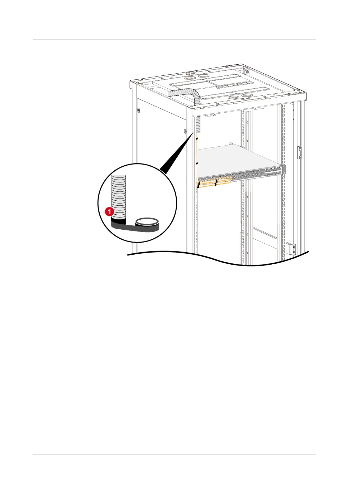
Figure 4-64 Inserting the corrugated pipe
6. Install the optical module, as shown in step 1 in Figure 4-65.
7. Route optical bers along the cable tray, remove the dust caps from the
optical modules and optical
ber interfaces. Then connect the end of each
optical ber to the corresponding optical interface, as shown in step 2 in
Figure 4-65.
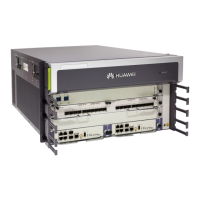
HUAWEI NetEngine 8000 F
Hardware Guide 4 Hardware Installation and Parts Replacement
Issue 05 (2023-03-31) Copyright © Huawei Technologies Co., Ltd. 418
 Loading...