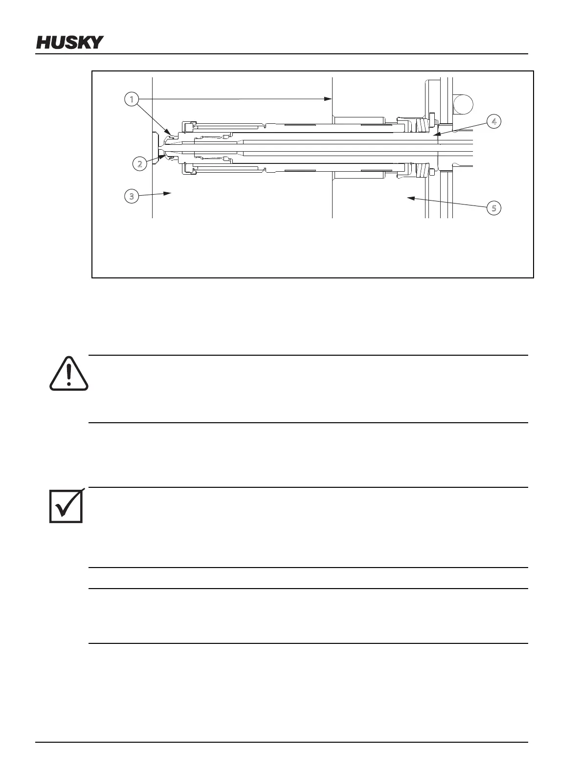
Figure 6-39: Cavity and Nozzle Sealing Diameters
1. Nozzle and Cavity Plate Sealing Diameters 2. Gate Bubble 3. Cavity Plate 4. Nozzle
Housing 5. Manifold Plate
3. Apply a static application grease to the hot runner alignment dowels. Refer to Section 3.9 for
information about recommended lubricants.
4. If equipped, install a nozzle tip insulator on each nozzle tip. Refer to Section 6.19 for more
information.
WARNING!
Crushing hazard – risk of death or serious injury. Inadequate lifting equipment can fail and
cause death or serious injury. Make sure all lifting equipment is rated for the load and in
safe operating condition.
5. Install hoist rings in the designated lifting points marked on the cavity plate.
6. Attach an overhead lifting device to the hoist rings and lift the cavity plate over the hot
runner.
IMPORTANT!
When assembling the cavity plate to the hot runner, special attention should be given to
preventing damage to the nozzle tips, valve stems and wires. The cavity plate should mate with
the hot runner without any resistance. If resistance is encountered, remove the plate and check
for any interference points.
CAUTION!
Mechanical hazard – risk of damage to equipment. Do not force the plate into position as
serious damage to the nozzle tips, valve stems and wires can result.
v 2.2 — March 2021 Unify Manifold System
100 Removing and Installing the Cavity Plate