DANGER!
Electrical hazard – risk of serious injury, re and/or overload of electrical components. Do
not use a controller with an amperage rating less than that required by the heaters. Do not
use a controller with a higher amperage rating than the connectors or cables to the hot
runner.
The type of controller can be either:
• Automatic control using a thermocouple to sense the nozzle tip temperature
• Manual control where the controller is set to provide power during a percentage of time
There may be an optional switchbox for turning ON or OFF the power to individual nozzle
heaters.
NOTE:
The controller output to the heaters must be set to 220 to 240 V, 50 to 60 Hz single phase.
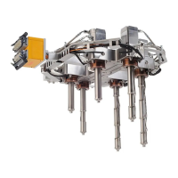
3.3.2 Nozzle Heaters
The nozzle heaters can be controlled separately or in zones by manual controllers. Refer to the
electrical schematic for the correct conguration.
3.3.3
Manifold Heaters
Whenever possible, the manifold heaters are wired in parallel and controlled by a single controller
zone. The circuit will be completed either at the cable connector or at the manifold.
The heaters are connected in multiple zones if the total amperage of all the heaters connected in
parallel exceeds the capacity of a single controller zone.
Each zone is connected to a separate controller zone with its own thermocouple.
3.3.3.1
Spare Thermocouple Wires
The temperature of each manifold heater zone is sensed by a J-type thermocouple.
NOTE:
Special order thermocouples may be other types.
A spare thermocouple for each zone is also be routed to the base of the multi-pin connector to
minimize down time. Should the main thermocouple fail, the spare can be easily connected
without having to disassemble the mold. The failed thermocouple can be replaced at the next
maintenance interval.
The spare thermocouples can also be used to verify the condition of the rst thermocouple
should a sensing problem develop.
v 2.2 — March 2021 Unify Manifold System
30 Nozzle Heaters