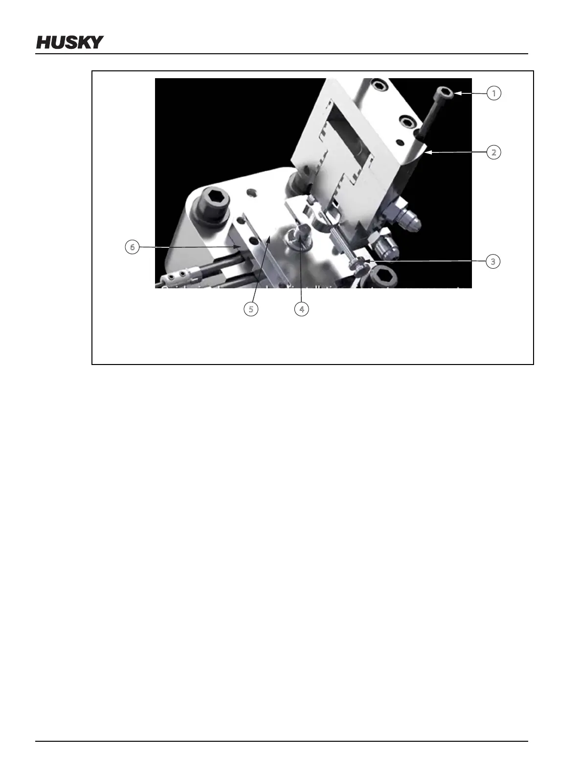
Figure 6-13: Removing and Installing an Actuator
1. Screw 2. Actuator 3. Spring Pin 4. Valve Stem 5. Shim 6. Bushing Cap
6. Push the spring pin to engage it with the valve stem.
7. Tighten the screws installed in step 5. Refer to the assembly drawings for torque
specications.
8. If equipped with a thermal regulator, connect the water hoses to the thermal regulator.
9. Connect the air hoses to the actuator.
6.7
Adjusting the Valve Stem Preload for Hydraulic Actuators
For VX style nozzle tips and tapered stem shut-o, where the stems shut-o on the nozzle tips,
Husky delivers the stem preload as identied on the assembly drawing.
For VG style nozzle tips, where tapered stems shut-o on a gate or cavity insert, Husky delivers
the stem preload as identied on the assembly drawing. This assumes that the gate insert L
dimension is within specication.
A shim is included in every hydraulic actuator assembly to control tapered valve stem preload.
To verify or change the valve stem preload for a hydraulic actuator, do the following:
1. Remove the hydraulic actuator and shim (refer to Section 6.5) from the nozzle drop to
expose the valve stem head. Make sure that the stem is in the fully forward (stem closed)
position.
2. Measure and record the stem seat depth of the piston in the cylinder assembly (Dimension
V) as shown in Figure 6-14.
v 2.2 — March 2021 Unify Manifold System
74 Adjusting the Valve Stem Preload for Hydraulic Actuators