10. Tighten the nozzle retainer.
11. Route the wires into the wire channel on the manifold frame. Make sure all wiring is properly
retained in the wire channel using wire clips.
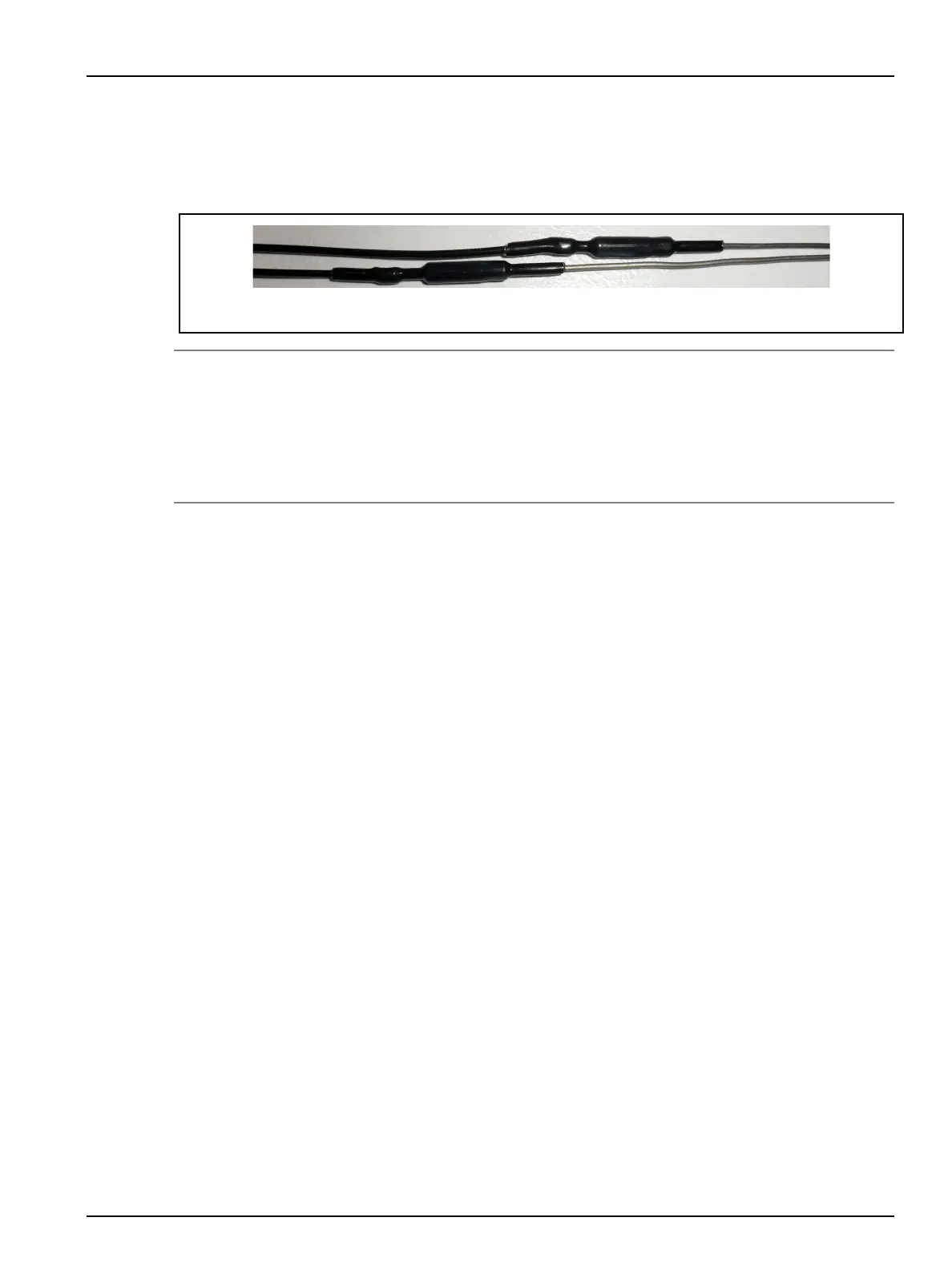
12. Make sure to stagger the knuckles in the wire grooves.
Figure 6-37: Staggering the Knuckles in the Wire Grooves
NOTE:
All wire, including heater or thermocouple wire, that could contact a heated component such as a
nozzle housing or manifold must be mineral insulated high temperature wire (hard lead). If the
mineral insulated lead is not long enough to allow this, additional steps must be taken, such as
using high temperature sleeving, to prevent the knuckles and PTFE or Kapton insulated wire (soft
lead) from overheating.
13.
Label each wire with the heater zone number. Refer to the electrical schematic for the zone
number.
14. Crimp the wire ends and connect the wires to the appropriate multi-pin connectors. Refer to
the electrical schematic for more information.
15. Test each nozzle heater. Refer to Section 6.13 for more information.
6.10.5
Removing and Installing HTM Nozzle Heaters for U1000 Systems
The following procedures describe how to remove and install HTM nozzle heaters for U1000
systems.
6.11
Replacing the Hydraulic or Pneumatic Manifold Hoses
Husky recommends that hydraulic or pneumatic manifold hoses be replaced after three years of
operation. Contact Husky for more information about the options below.
• To replace the hoses, return the Unify system to Husky. Husky will assemble, correctly route
and test the new hoses.
• Order a complete hose package from Husky.
• To order a single hose, contact Husky support and provide the following information for the
hose that needs to be replaced: drop number, uid type, open/close (for hydraulic uid), or
in/out (for water).
Hot Runner Installation Manual v 2.2 — March 2021 Maintenance
Removing and Installing Nozzle Heaters 95