NOTE:
To establish proper polarity when connecting thermocouples, follow the electrical schematic. For
J-type thermocouples, the white wire is positive (+) and the red wire is negative (-). This wire color
coding follows the ANSI J-Type North American Standard. The color coding and wire composition
for J-type thermocouples in other parts of the world may be dierent and produce dierent
readings.
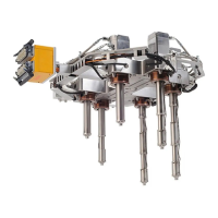
3.3.4 Power Fluctuation
Hot runner systems are sensitive to uctuations in power supply voltage. The nozzle and manifold
heaters are rated for 240 V (or 200 V in special applications).
NOTE:
Always refer to the hot runner nameplate on the operator’s side of the clamp before installing a
hot runner. For more information on the nameplate, refer to Section 1.7.
The manifold is always controlled by thermocouples and will compensate for minor voltage
uctuations.
Where the nozzle heaters are regulated by percentage timers, the heat output will be directly
aected by voltage uctuations. For example, a reduction of the voltage by only 10% will aect
output (in Watts) by approximately 20%, which will reduce the nozzle temperatures considerably.
Adjustment is required.
In severe cases where the stability of the power supply is known to be unreliable, it may be
advisable to install an automatic voltage stabilizer rated for the power requirements of the
controller.
3.4
Operating Specications
The operating specications depend on the type of manifold being used.
3.4.1
Hydraulic Manifold Operating Limits
Fluid Type Description Value
Hydraulic uid Maximum operating pressure 40 bar (580 psi) - 50 bar (725 psi)
[1]
Maximum operating ow rate 9.5 L/min (2.5 U.S. gal./min)
Cooling water Maximum operating pressure 8 bar (116 psi)
Minimum operating ow rate 2 L/min (0.53 U.S. gal./min) per actuator
Maximum water temperature 35 °C (95 °F)
Hot Runner Installation Manual v 2.2 — March 2021 Specications
Electrical System Specications 31