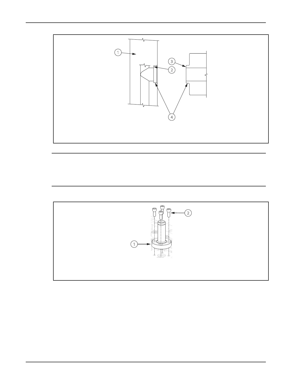
Figure 6-51: Sprue Bushing and Manifold Sealing Faces
1. Manifold 2. Spigot Pocket Face 3. Spigot Face 4. Locating Diameters
CAUTION!
Crushing hazard – risk of damage to equipment. Screws used to install the sprue bushing
must meet specic requirements. Only use the screws specied in the assembly drawings.
Failure to use these screws could result in equipment damage.
2. Apply a high temperature anti-seize lubricant to the screws used to install the sprue bushing.
Refer to Section 3.5 for information about recommended lubricants.
Figure 6-52: Installing the Sprue Bushing
1. Sprue Bushing 2. Screw
3. Install the sprue bushing and torque all screws to half the specied value in a cross pattern.
Refer to the assembly drawings for torque requirements.
4. Torque the screws fully to the specied value to make sure an even seal is made between the
sprue bushing and manifold. Refer to the assembly drawings for torque requirements.
5. Install the sprue heater. Refer to Section 6.17 for more information.
6. Install the hot runner into the machine. Refer to Section 4.2 for more information.
Hot Runner Installation Manual v 2.2 — March 2021 Maintenance
Removing and Installing the Sprue Bushing 117