NOTE:
If the heater and thermocouple do not spring back to the snap ring or maintain contact with each
other, the bends in the wiring may be at fault.
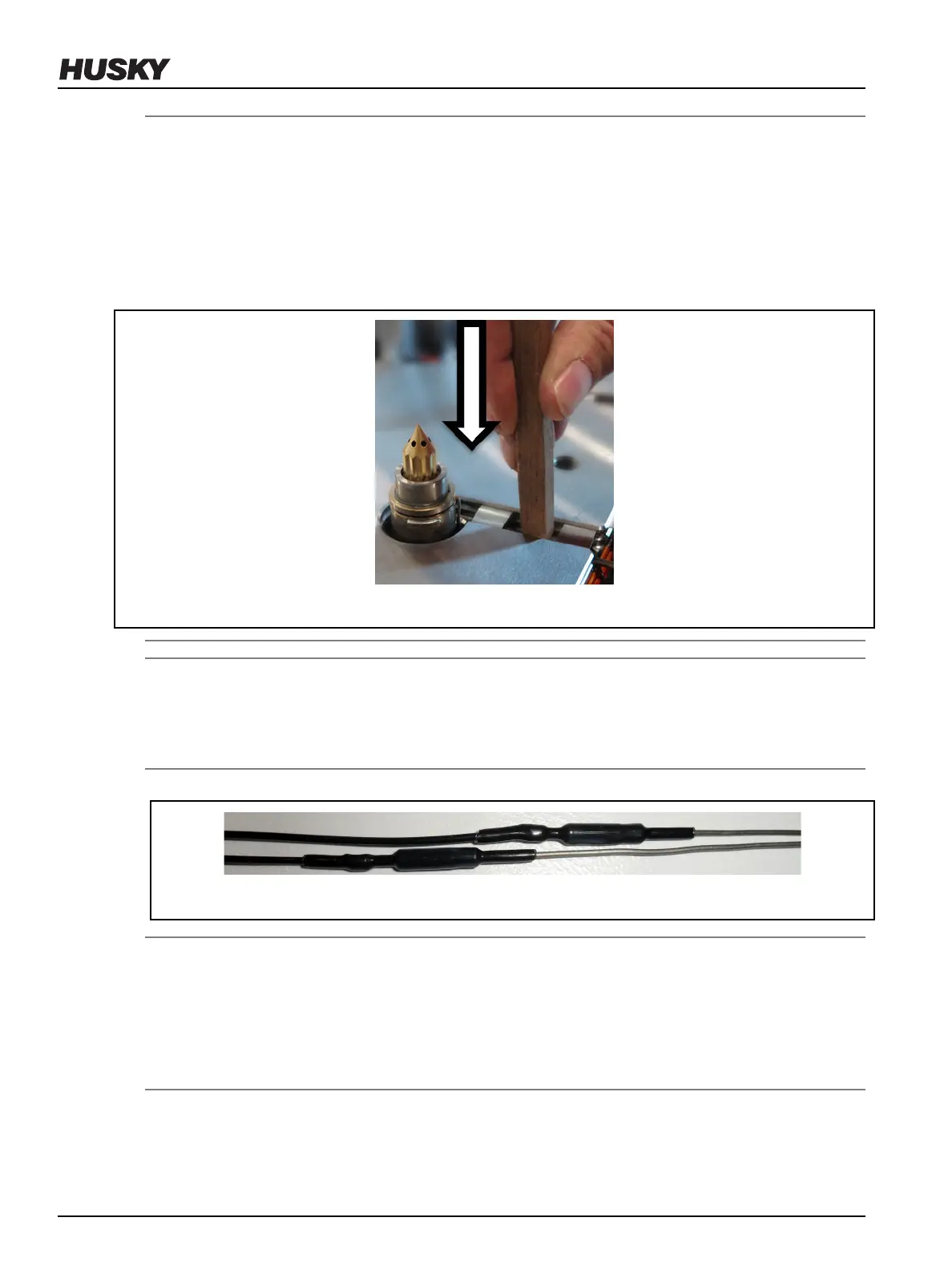
• Wire routing must not over constrain heater positioning on nozzle.
• Wiring contacting a wire groove clip can restrict spring-back motion.
• Adjust wiring by pushing it down towards the bottom of the wire groove.
• Wiring must not protrude above the plate surface.
Figure 6-28: Wiring Placement in Groove
NOTE:
Proper operation of the Ultra Nozzle Heater requires the force of the wave spring to maintain
contact between the thermocouple ring and nozzle heater. Improper installation may result in
processing issues.
8. Make sure to stagger the knuckles in the wire grooves.
Figure 6-29: Staggering the Knuckles in the Wire Grooves
NOTE:
All wire, including heater or thermocouple wire, that could contact a heated component such as a
nozzle housing or manifold must be mineral insulated high temperature wire (hard lead). If the
mineral insulated lead is not long enough to allow this, additional steps must be taken, such as
using high temperature sleeving, to prevent the knuckles and PTFE or Kapton insulated wire (soft
lead) from overheating.
9. Label each wire with the heater zone number. Refer to the electrical schematic for the zone
number.
v 2.2 — March 2021 Unify Manifold System
88 Removing and Installing Nozzle Heaters