Chapter 5 I/O Parameter
117
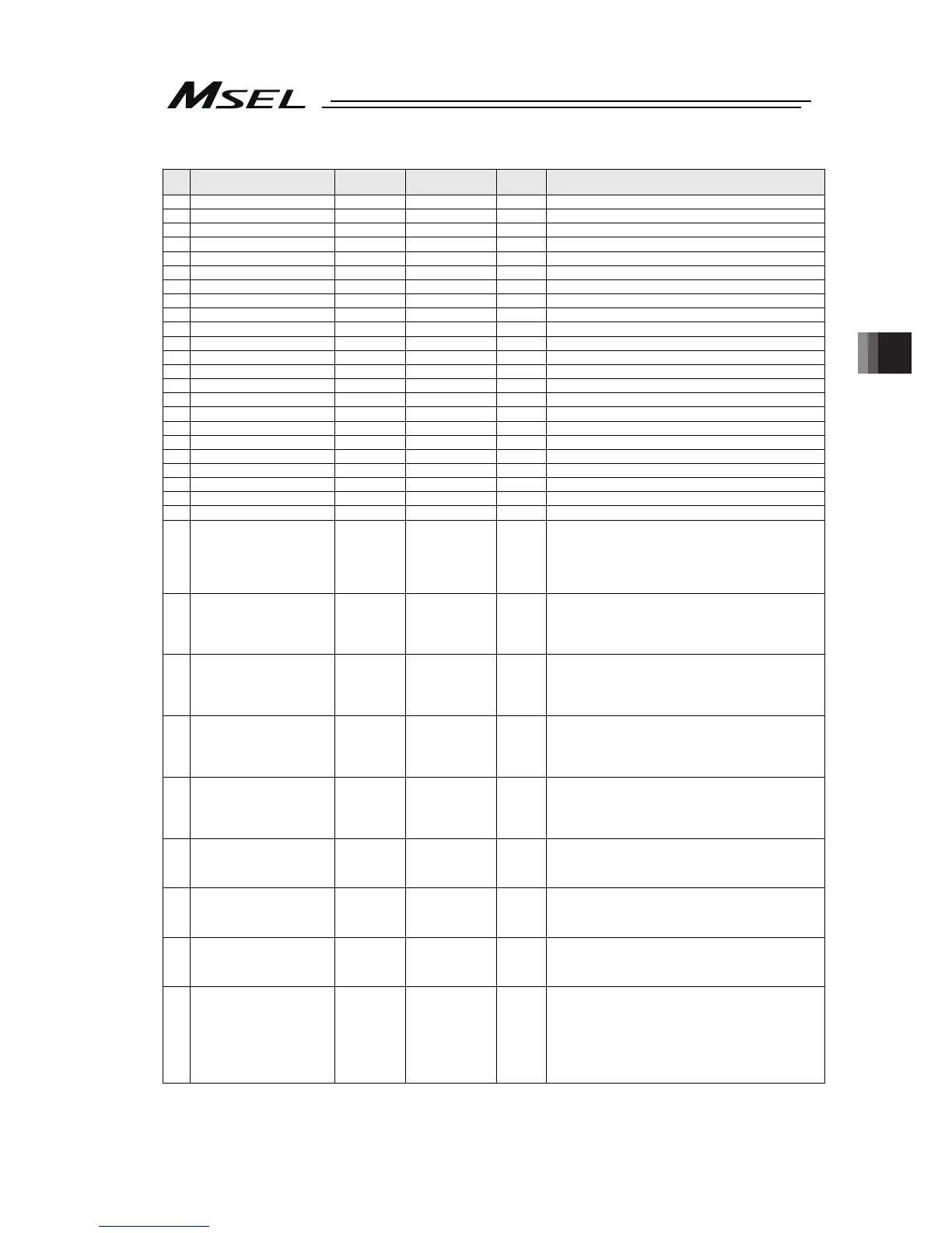
All Axes Common Parameters
No. Parameter name
Default value
(Reference)
Input range Unit Remarks
98 (For extension) 0 ~
99 (For extension) 0 ~
100 (For extension) 0 ~
101 (For extension) 0 ~
102 (For extension) 0 ~
103 (For extension) 0 ~
104 (For extension) 0 ~
105 (For extension) 0 ~
106 (For extension) 0 ~
107 (For extension) 0 ~
108 (For extension) 0 ~
109 (For extension) 0 ~
110 (For extension) 0 ~
111 (For extension) 0 ~
112 (For extension) 0 ~
113 (For extension) 0 ~
114 (For extension) 0 ~
115 (For extension) 0 ~
116 (For extension) 0 ~
117 (For extension) 0 ~
118 (For extension) 0 ~
119 (For extension) 0 ~
120 (For extension) 0 ~
121
Vision system I/F 1
Coordinate axis definition
(For PC/PG/PCF/PGF type)
4321H 0H ~ FFFFFFFFH
* PCX/PGX is system reservation
Bits 0 to 3: Axis number in X direction
Bits 4 to 7: Axis number in Y direction
Bits 8 to 11: Axis number in Z direction
Bits 12 to 15: Axis number in R direction
Bits 16 to 31: Reserved
122
Vision system I/F 1
Coordinate datum point offset
X
(For PC/PG/PCF/PGF type)
0
-99999999 ~
99999999
0.001mm
* PCX/PGX is system reservation
Robot coordinate X on vision system I/F 1 coordinate (X
= 0, Y = 0)
* Setting is to be established at vision system I/F
adjustment.
123
Vision system I/F 1
coordinate datum point offset
Y
(For PC/PG/PCF/PGF type)
0
-99999999 ~
99999999
0.001mm
* PCX/PGX is system reservation
Robot coordinate Y on vision system I/F 1 coordinate (X = 0,
Y = 0)
* Setting is to be established at vision system I/F
adjustment.
124
Vision system I/F 1
coordinate offset angle
(For PC/PG/PCF/PGF type)
0
-99999999 ~
99999999
0.001deg
* PCX/PGX is system reservation
Rotation angle of vision system I/F 1 coordinate when robot
coordinate is taken as the datum
* Setting is to be established at vision system I/F
adjustment.
125
Vision system I/F 1
Z-axis direction vision system
position judgment datum
(For PC/PG/PCF/PGF type)
0
-99999999 ~
99999999
0.001mm
* PCX/PGX is system reservation
(Related Information: All Axes Parameter No. 130)
* Setting is to be established at vision system I/F
adjustment.
126
Vision system I/F 1
X-axis (GTVD acquirement
data) adjustment offset
(For PC/PG/PCF/PGF type)
0 -99999 ~ 99999 0.001mm * PCX/PGX is system reservation
127
Vision system I/F 1
Y-Axis (GTVD acquirement
data) adjustment offset
(For PC/PG/PCF/PGF type)
0 -999999 ~ 99999 0.001mm * PCX/PGX is system reservation
128
Vision system I/F 1
R-Axis (GTVD acquirement
data) adjustment offset
(For PC/PG/PCF/PGF type)
0 -360000 ~ 360000 0.001deg * PCX/PGX is system reservation
129
Vision System I/F 1 Control 1
(For PC/PG/PCF/PGF type)
0H 0H ~ FFFFFFFFH
* PCX/PGX is system reservation
Bits 0 to 3: System reservation (Change prohibited)
Bits 4 to 11: System reservation (Change prohibited)
Bits 12 to 19: System reservation (Change prohibited)
Bits 20 to 23: R-axis adjustment sign reverse
( 0: Not to reverse code
1: Reverse code)
Bits 24 to 31: Reserved

 Loading...


