Chapter 7 Appendix
214
(1) Setting the tool coordinate system
Set the offset amount from the tool attached position to the tool tip.
Set the tool offset as explained below under condition that each axis system coordinates for
all the unit constructing axes is 0 is taken as the datum.
x Example for Tool Coordinate System Setting
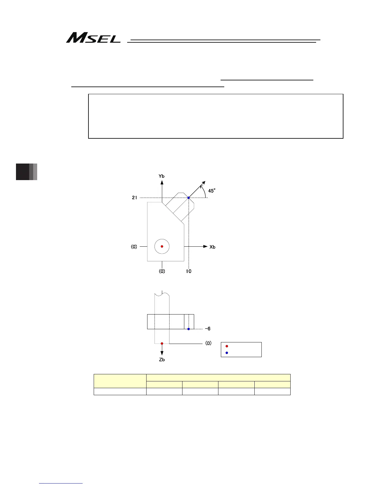
When required to set Tool Coordinate System No. 1 as shown in the figure below;
(The figure below is assumed to show that each axis system coordinates for all the unit
constructing axes is 0)
P
T0
ツール先端
The offset of Tool Coordinate System No. 1 are to be set as shown in the table below.
Tool Coordinate
System No.
Offset
X [mm] Y [mm] Z [mm] R [deg]
1 10.000 21.000 -6.000 45.000
・X, Y, Z offset
Distance from the tool attached position to the tool tip along Xb, Yb and Zb directions of the
base coordinate system
・R offset
Angle of the working direction with Xb positive direction as the datum
(Definition for direction of angle is the same as work coordinate system R offset)
Tool tip

 Loading...


