16
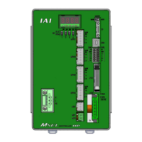
10) System I/O connector
It is the input and output connectors to manage the safety control on the controller.
For PG / PGX types (safety category complied), it is available to comply with up to
category 3 by connecting an external safety circuit to this controller.
11) Standard I/O connector
It is the connector to apply PIO signals of 16 points each of general-purposed input and
output.
12) Status LED for extension I/O
It shows the status of PIO or fieldbus plugged to the extension I/O connector.
[Refer to Status LED in Section 3.3.3]
13) Extension I/O connector
It is equipped when PIO or fieldbus is selected as the extension I/O. It is a connector for
the general-purposed I/O signal for PIO type and for connection of each fieldbus for
fieldbus type.
14) Motor drive power supply line connector
It is generally used by short-circuiting MPI and MPO. When supply / cut off the motor
driving power externally to construct the safety circuit, connect a contact point between
MPI and MPO.

 Loading...