LED Assembly Removal
1.
Position System Unit Power switch to Off, unplug System Unit
power cord, and disconnect all cables from rear
of
System
Unit.
2.
Set Display, Keyboard, and Printer away from System Unit
~
working area.
~
3.
Remove System Unit cover (See page 3-98).
4. Remove Diskette Drive Logic Printed Circuit Board
(See page 3-24).
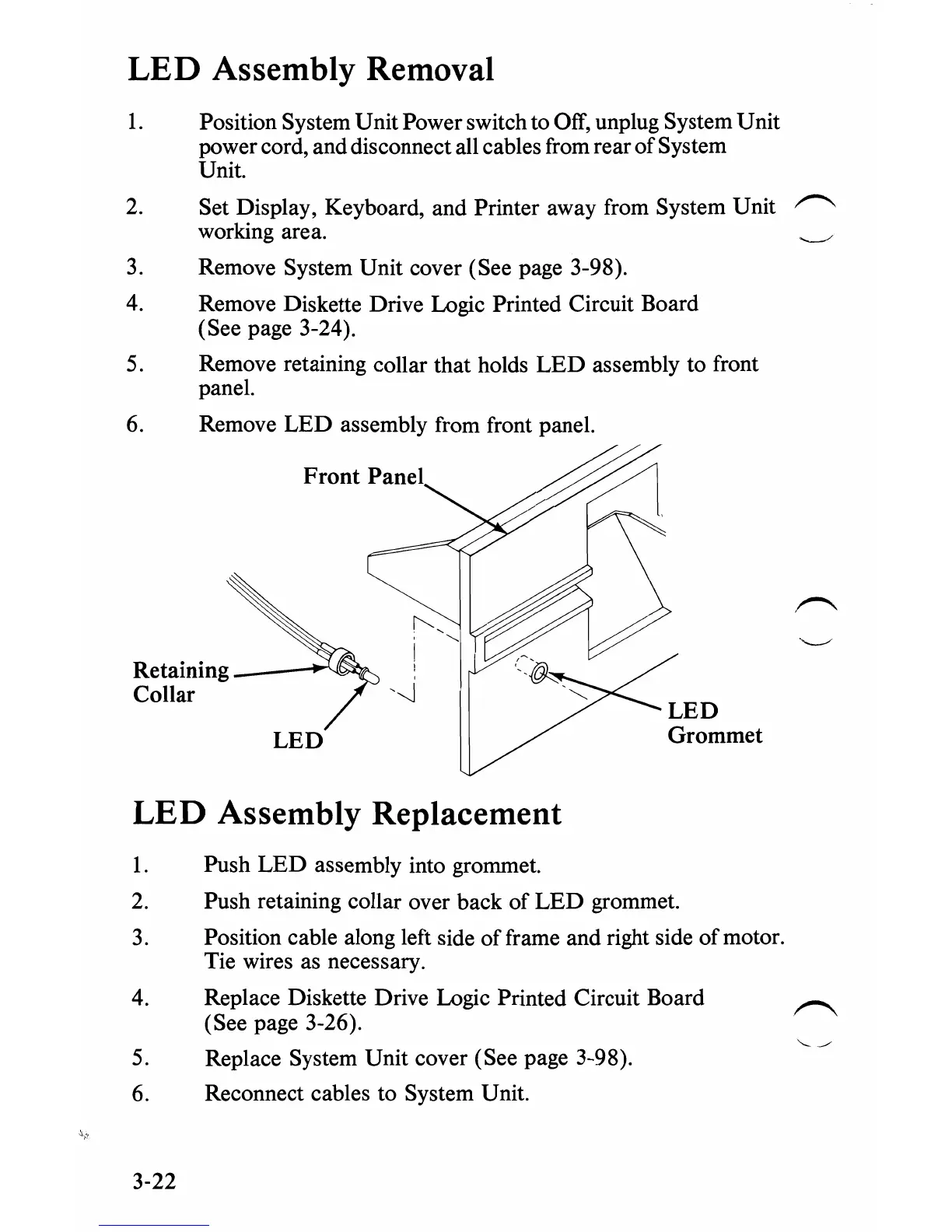
5.
Remove retaining collar that holds
LED
assembly to front
panel.
6. Remove
LED
assembly from front panel.
Front
panel/;~~
Retaining
------;~~
Collar
LED
Grommet
LED
LED Assembly Replacement
1.
Push
LED
assembly into grommet.
2.
Push retaining collar over back of
LED
grommet.
3.
Position cable along left side offrame and right side of motor.
Tie wires as necessary.
4. Replace Diskette Drive Logic Printed Circuit Board
(See page 3-26).
5.
Replace System Unit cover (See page 3-98).
6.
Reconnect cables to System Unit.
3-22
 Loading...


