EasyManuals Logo

IBM 5150 Hardware Maintenance Manual

IBM 5150
357 pages
To Next Page IconTo Next Page
To Previous Page IconTo Previous Page
Page #206 background imageLoading...
Page #206 background image
Write Protect Switch Assembly Replacement
1.
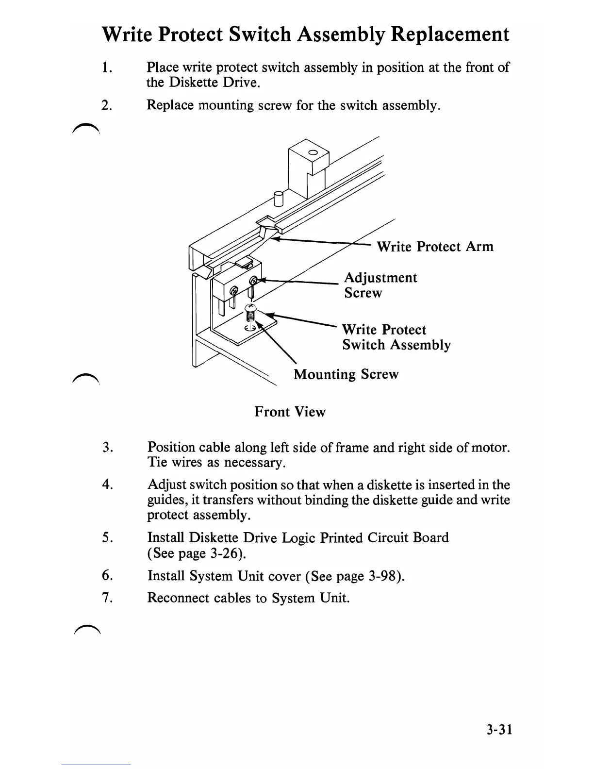
Place write protect switch assembly in position at the front of
the Diskette Drive.
2.
Replace mounting screw for the switch assembly.
r"'\
Write Protect Arm
1fJ7'f--;::""':;---
Adjustment
Screw
Write Protect
Switch Assembly
Front
View
3.
Position cable along left side offrame and right side
of
motor.
Tie wires as necessary.
4.
Adjust switch position so that when a diskette
is
inserted in the
guides, it transfers without binding the diskette guide and write
protect assembly.
5.
Install Diskette Drive Logic Printed Circuit Board
(See page 3-26).
6. Install System Unit cover (See page 3-98).
7.
Reconnect cables to System Unit.
3-31

Table of Contents

Other manuals for IBM 5150

Questions and Answers:

Question and Answer IconNeed help?

Do you have a question about the IBM 5150 and is the answer not in the manual?

IBM 5150 Specifications

General IconGeneral
ProcessorIntel 8088
Clock Speed4.77 MHz
RAM16 KB - 256 KB
ManufacturerIBM
Model5150
Release Year1981
Storage5.25-inch floppy drives
GraphicsMDA or CGA
Operating SystemIBM PC DOS
PortsCassette, keyboard
Expansion Slots5

Related product manuals