EasyManuals Logo

IBM 5150 Hardware Maintenance Manual

IBM 5150
357 pages
To Next Page IconTo Next Page
To Previous Page IconTo Previous Page
Page #243 background imageLoading...
Page #243 background image
Left Margin Adjustment (continued)
12.
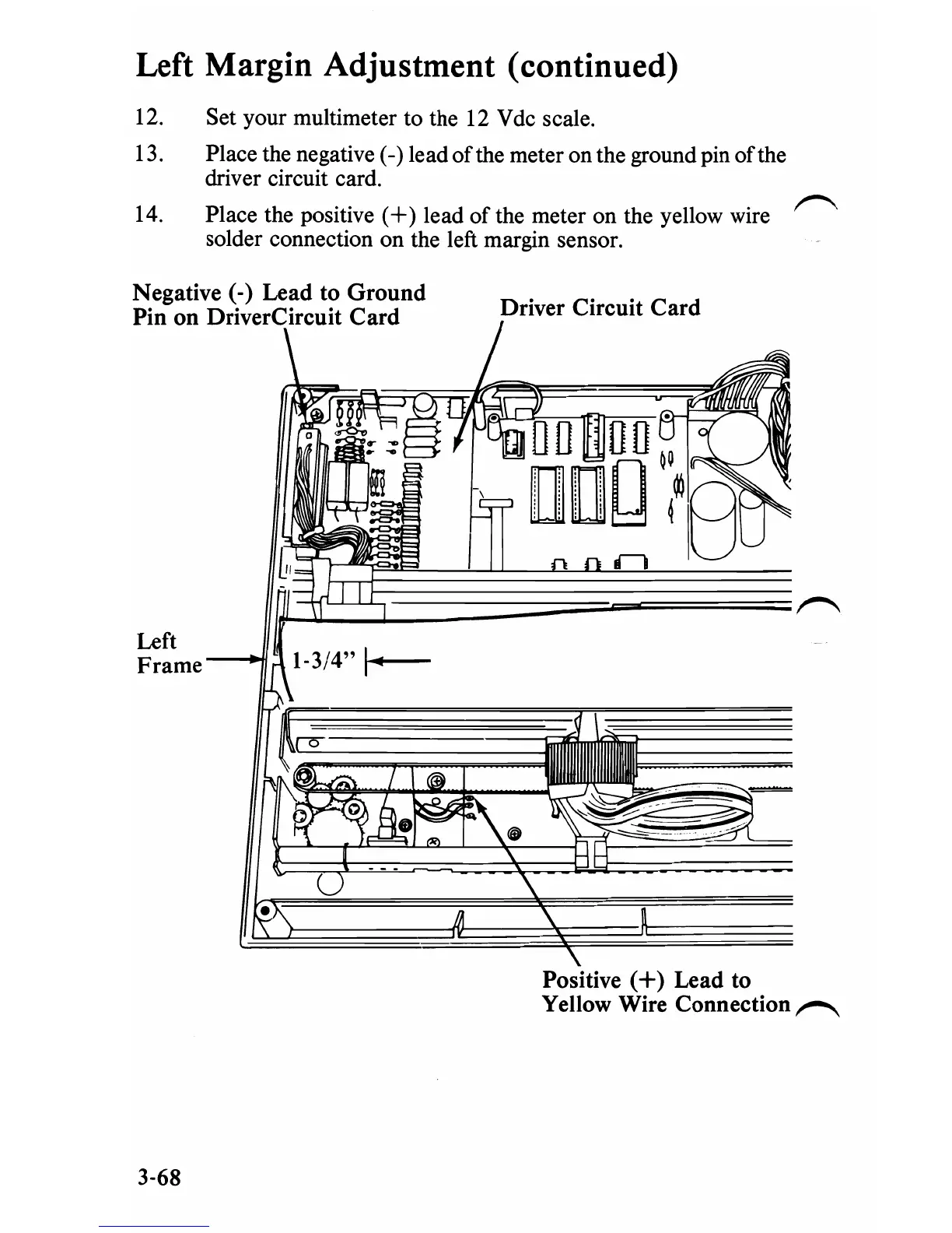
Set your multimeter to the 12 V dc scale.
13.
Place the negative (-) lead
of
the meter on the ground pin
of
the
driver circuit card.
~
14.
Place the positive
(+)
lead
of
the meter on the yellow wire
solder connection on the left margin sensor.
Negative (-) Lead to
Ground
Driver Circuit
Card
Pin
on
DriverCircuit
Card
Left
Frame
Positive
(+)
Lead
to
Yellow Wire Connection
~
3-68

Table of Contents

Other manuals for IBM 5150

Questions and Answers:

Question and Answer IconNeed help?

Do you have a question about the IBM 5150 and is the answer not in the manual?

IBM 5150 Specifications

General IconGeneral
ProcessorIntel 8088
Clock Speed4.77 MHz
RAM16 KB - 256 KB
ManufacturerIBM
Model5150
Release Year1981
Storage5.25-inch floppy drives
GraphicsMDA or CGA
Operating SystemIBM PC DOS
PortsCassette, keyboard
Expansion Slots5

Related product manuals