22. Tighten the Printer Timing Sensor locking screw and recheck
step 21. Realign if necessary.
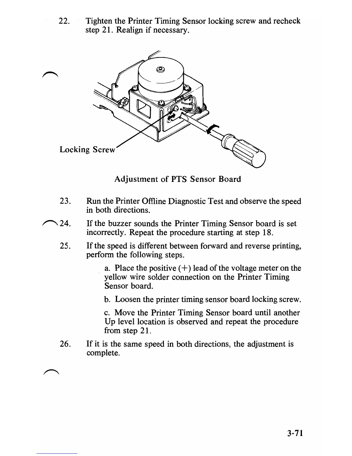
Locking Screw
Adjustment
of
PTS
Sensor
Board
23. Run the Printer Omine Diagnostic Test and observe the speed
in both directions.
~24.
If
the buzzer sounds the Printer Timing Sensor board
is
set
incorrectly. Repeat the procedure starting at step 18.
25.
If
the speed is different between forward and reverse printing,
perform the following steps.
a.
Place the positive
(+
) lead
of
the voltage meter on the
yellow wire solder connection on the Printer Timing
Sensor board.
b.
Loosen the printer timing sensor board locking screw.
c.
Move the Printer Timing Sensor board until another
Up level location
is
observed and repeat the procedure
from step 21.
26.
If
it
is
the same speed in both directions, the adjustment is
complete.
3-71
 Loading...


