Left Margin Adjustment (continued)
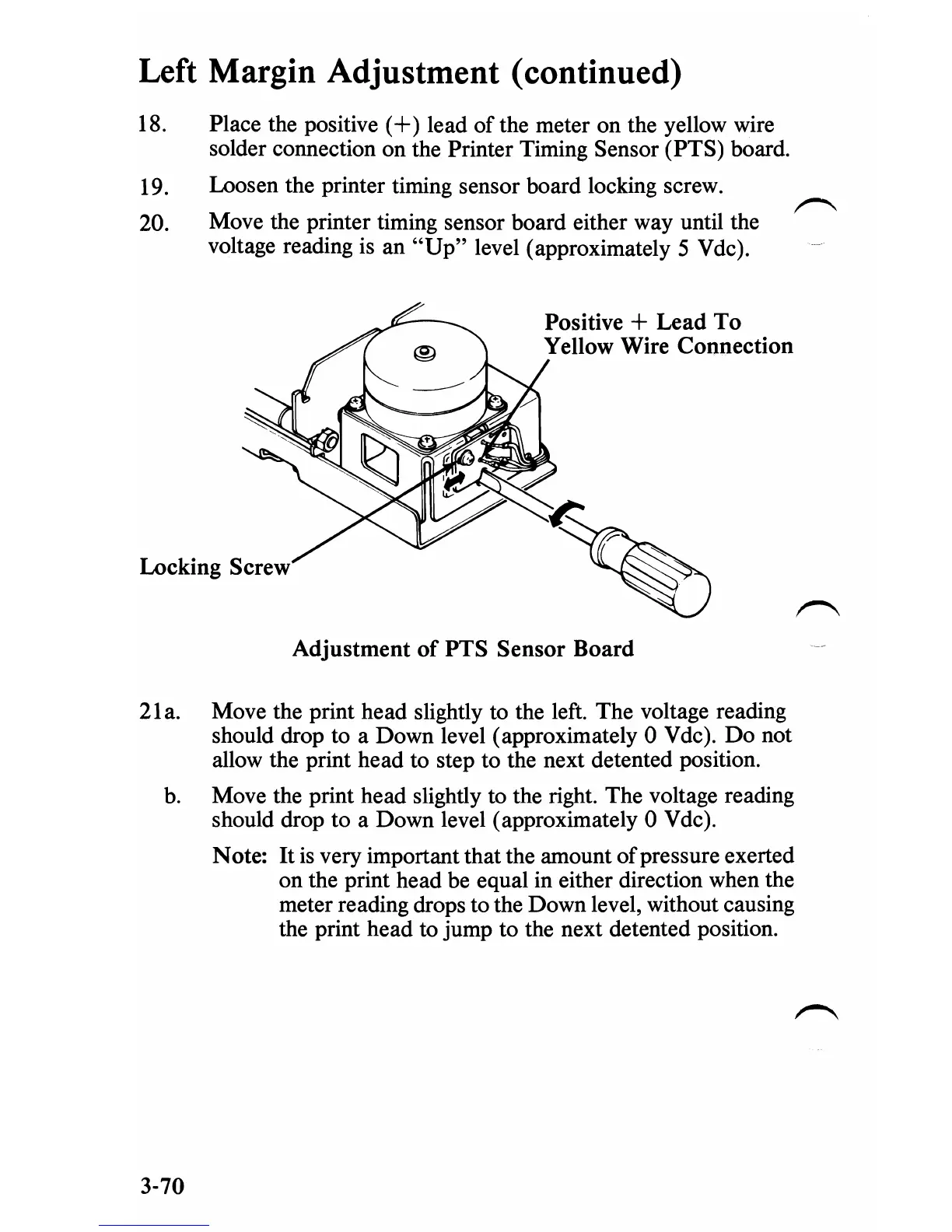
18. Place the positive
(+)
lead
of
the meter on the yellow wire
solder connection on the Printer Timing Sensor (PTS) board.
19.
Loosen the printer timing sensor board locking screw.
20.
Move the printer timing sensor board either way until the
voltage reading is an
"Up"
level (approximately 5 V dc).
Positive
+ Lead
To
Yellow Wire Connection
Locking Screw
Adjustment
of
PTS
Sensor Board
21
a.
Move the print head slightly to the left. The voltage reading
should drop to a Down level (approximately 0 V dc).
Do
not
allow the print head to step to the next detented position.
b.
Move the print head slightly to the right. The voltage reading
should drop to a Down level (approximately 0 V dc).
Note:
It
is
very important that the amount
of
pressure exerted
on the print head be equal in either direction when the
meter reading drops to the Down level, without causing
the print head to jump to the next detented position.
3-70

 Loading...


