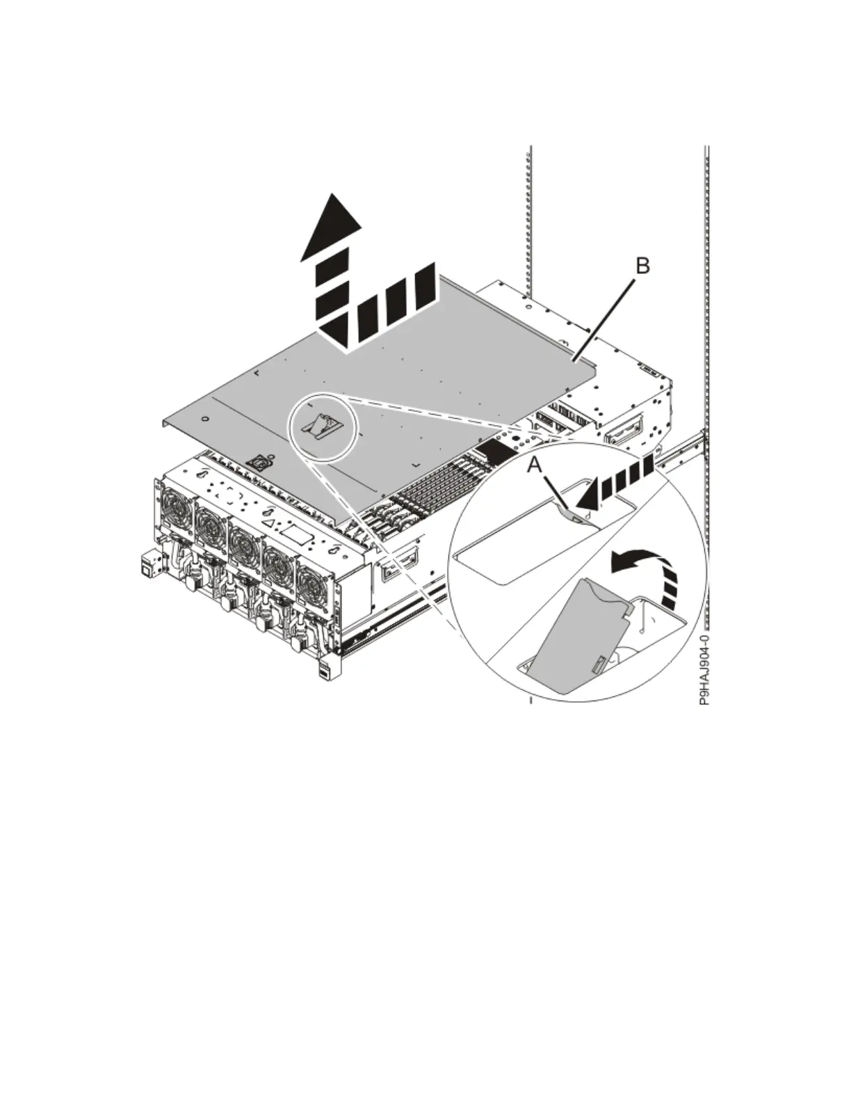
a. Push the release latch (A) in the direction shown in the following gure.
b. Slide the cover (B) off the system unit as shown in the following gure. When the service access
cover has cleared the upper frame ledge, lift the cover up and off the system unit.
Figure 100. Removing the service access cover
7. To activate the identify LED for the locations for installing the memory modules, press and hold either
push-button on the trusted platform module card as shown in the following gure.
Verify that the LED (A) is lit, which indicates that sufcient power exists for the identify LED. If the LED
is not lit, use the location code to nd the physical location by using the service label.
Memory modules
117

 Loading...