b) In the navigation area, expand System Service Aids > Cable Plugging Validation. Then, click
Validate Cables. The system veries that the expected cables are present.
c) If your conguration includes two or more nodes, expand System Service Aids > Cable Plugging
Validation. Then, click Verify Node Position. Otherwise, if your conguration includes only one
node, continue to the next step.
If the system is cabled correctly, the blue identify LED on each system node will light up, in
sequence, from the top node to the bottom node. If the LEDs do not light up in sequence, the FSP
cables need to be re-installed.
d) Expand System Service Aids > Cable Plugging Validation. Then, select All of the above in the
Display Cable Status section and click Continue. The system validates that the cables are
installed in the correct locations. Expand System Service Aids > Cable Plugging Validation to
display a table with the results. Ensure that the plugging status is OK for each cable in the
displayed table. If the status is OK, no further action is required. If the status is not OK, review the
error logs, correct the problems, and repeat steps b, c and d as needed until the status is OK for
all cables.
e) Exit the ASMI.
Removing and replacing memory modules
Preparing the 9080-M9S system to remove and replace a memory module
Procedure
1. Open the rear rack door, if necessary.
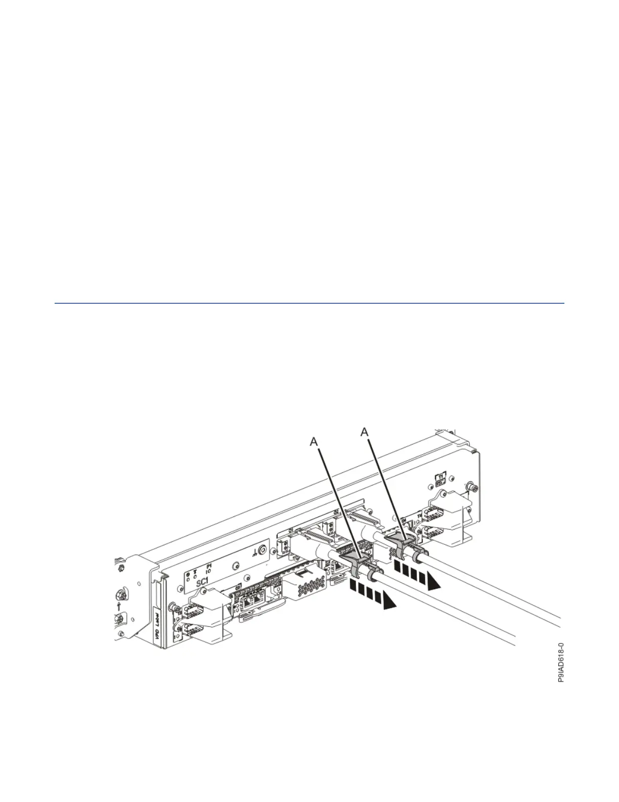
2. Label and disconnect both UPIC cables from the system control unit.
UPIC cable locations are P1-C1-T1 and P1-C2-T1.
a. Remove the white plastic lock (A) from the plug housing.
Figure 128. Removing the UPIC cable lock
b. Push down on the blue cable latch (B) and pull out the UPIC cable from the system control unit.
Memory modules
149

 Loading...