6. If applicable, loosen the hook-and-loop fastener securing the cable to the rack.
Replacing a UPIC cable in the 9080-M9S system
To replace a UPIC cable in the system, complete the steps in this procedure.
Procedure
1. Ensure that you have the electrostatic discharge (ESD) wrist strap on and that the ESD clip is plugged
into a ground jack or connected to an unpainted metal surface. If not, do so now.
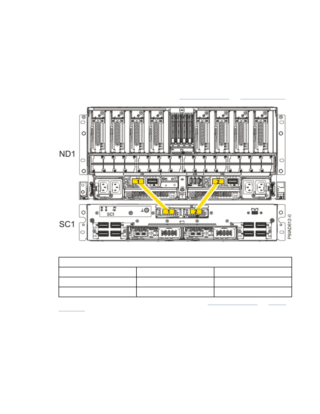
2. Refer to the following information to determine the point-to-point cabling for UPIC cables.
• If you have a single node system conguration, use Figure 43 on page 50
and Table 5 on page 50
to determine the point-to-point cabling for UPIC cables.
Figure 43. Single Node
Conguration UPIC Cabling
Table 5. Single Node
Conguration UPIC Cabling
Cable number From To
1 SC1: P1-C1-T1 ND1: P1-C9-T1
2 SC1: P1-C2-T1 ND1: P1-C10-T1
• If you have a two, three, or four node system conguration, use Figure 44 on page 51 and Table 6
on page 51 to determine the point-to-point cabling for UPIC cables.
50
Power Systems: Removing and replacing parts in the 9080-M9S system

 Loading...