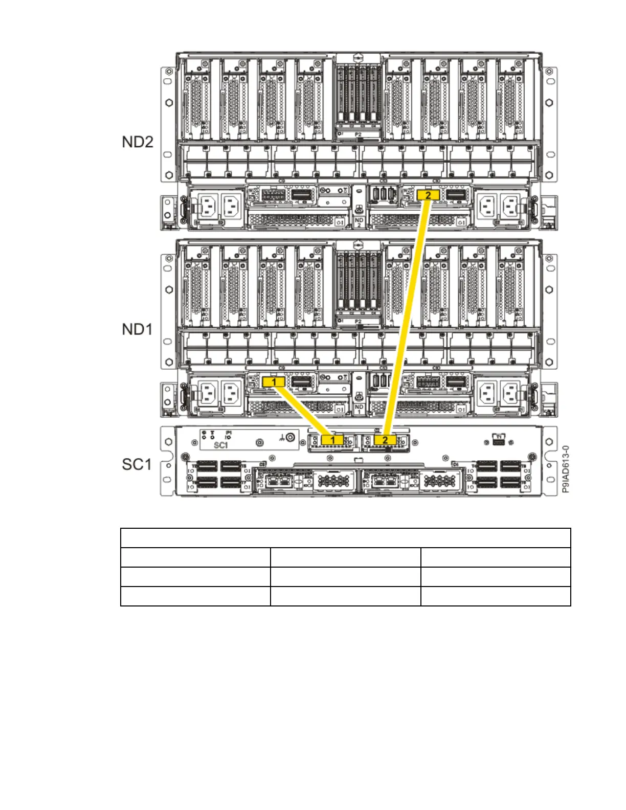
Figure 238. Two, Three, or Four Node Conguration UPIC Cabling
Table 37. Two, Three, or Four Node
Conguration UPIC Cabling
Cable From To
1 SC1: P1-C1-T1 ND1: P1-C9-T1
2 SC1: P1-C2-T1 ND2: P1-C10-T1
a) To replace the UPIC cable in the system node, complete the following steps:
1) Ensure that the white plastic lock is pulled back from the plug housing.
2) Plug the UPIC cable (A) into the previously identied location in the system node by inserting
the cable into the connector until it locks into place, as shown in the following gure.
278
Power Systems: Removing and replacing parts in the 9080-M9S system

 Loading...