Table 45. Service processor (FSP) cable locations
Drawer Cable Cable Length From To
ND4 (top) A 1330 mm (4.36 ft) SC1-P1-T7 ND4-P1-C9-T2
B 1330 mm (4.36 ft) SC1-P1-T9 ND4-P1-C10-T2
ND3 A 1110 mm (3.64 ft) SC1-P1-T6 ND3-P1-C9-T2
B 1110 mm (3.64 ft) SC1-P1-T8 ND3-P1-C10-T2
ND2 A 855 mm (2.81 ft) SC1-P1-T2 ND2-P1-C9-T2
B 855 mm (2.81 ft) SC1-P1-T4 ND2-P1-C10-T2
ND1 (bottom) A 355 mm (1.16 ft) SC1-P1-T3 ND1-P1-C9-T2
B 355 mm (1.16 ft) SC1-P1-T5 ND1-P1-C10-T2
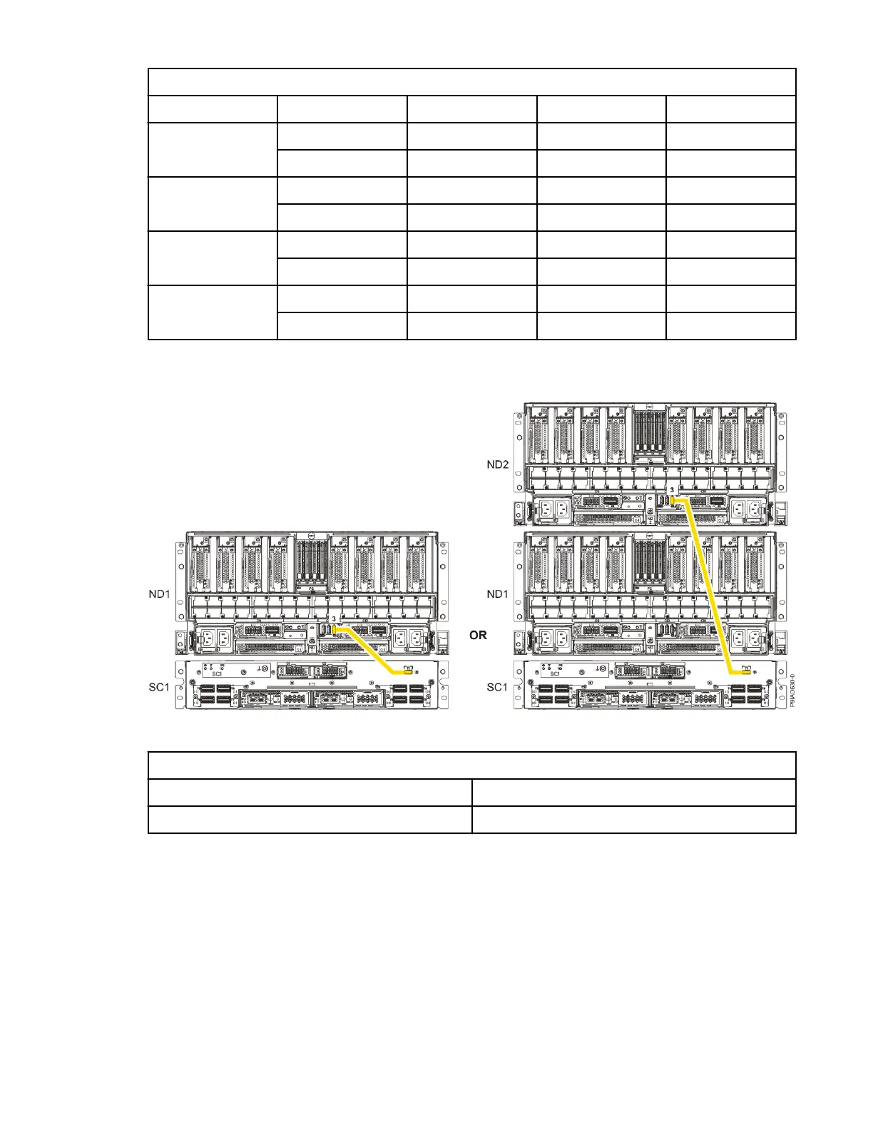
7. Review the following information to identify the locations where the USB cable connects to the
system node that you are servicing and to the system control unit. Then, reconnect the USB cable
that you removed.
Figure 282. USB Cabling
Table 46. USB Cabling
From To
ND1 or ND2: P1-C13-T3 SC1: P1-T1
a) Plug the USB cable into the previously identied location in the system node by inserting the cable
into the connector, as shown in the following gure.
330
Power Systems: Removing and replacing parts in the 9080-M9S system

 Loading...