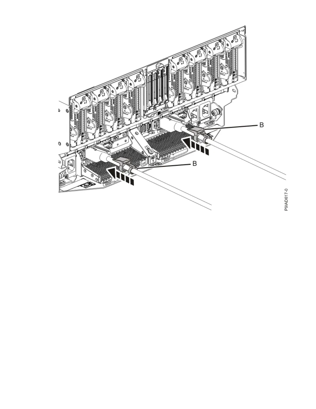
Figure 46. Replacing the UPIC cable into the system node
d. Lightly pull on the UPIC cable from both attachment points to ensure it is locked into place. Pull the
cable connector; do not pull on the wire. The cables should be rmly attached to the system.
4. To replace the UPIC cable in the system control unit, complete the following steps:
UPIC cable locations are P1-C1-T1 and P1-C2-T1.
a. Ensure that the white plastic lock is pulled back from the plug housing.
b. Plug the UPIC cable (A) into the previously identied location in the system control unit by inserting
the cable into the connector until it locks into place.
Cables
53

 Loading...