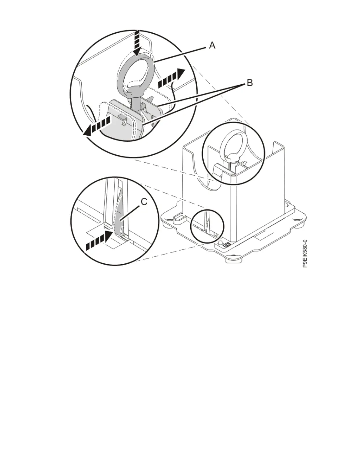
Figure 537. Locking the system processor module into the tool
c) Hold the sides of the tool with system processor module and carefully lift the tool out of the
system processor module tray.
d) Lower the tool and system processor module onto the socket from which you just removed a dust
cover. Align the beveled corner of the tool with the beveled corner on the socket. Align the guide
pins (A) with the alignment holes (B) on each side of the tool. Use care to lower the tool evenly
without tilting the tool. Refer to the following gure.
Note: Do not attempt to slide the tool and the system processor module in any direction while the
system processor module is touching the socket. If the tool and the system processor module are
not aligned with the guide pins, lift the tool and the system processor module and reposition
them.
System backplanes
615

 Loading...