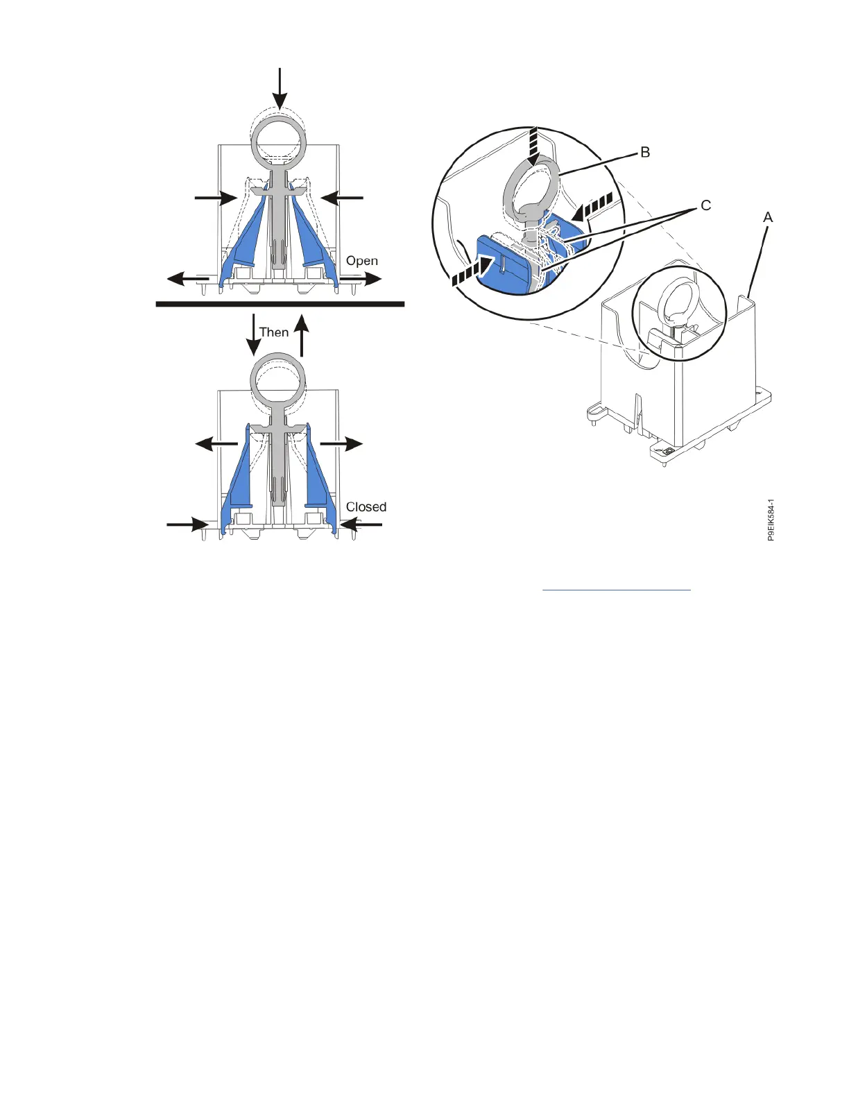
Figure 572. Ensuring that the removal tool is in the open position
b) Lower the tool over the system processor module as shown in Figure 573 on page 653. Ensure
that the beveled edge on the tool aligns with the beveled edge of the system processor module.
Ensure that the two guide pins (A) are inserted into the alignment holes (B) on each side of the tool.
652
Power Systems: Removing and replacing parts in the 9080-M9S system

 Loading...