Table 22. Description of Figure 53 (continued)
Number Description
18 EXP810 enclosure 14
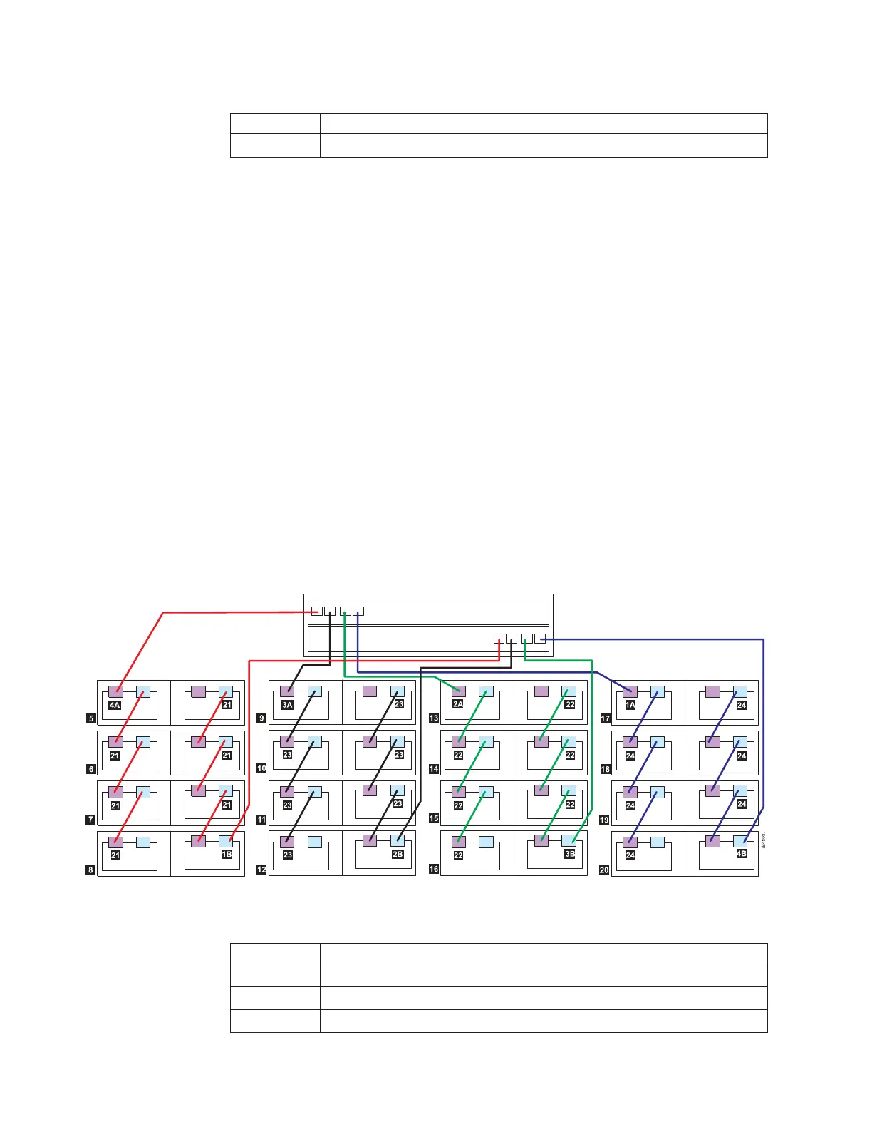
1. Make all connections from the left ESMs to the right ESMs in the expansion
enclosures, as indicated by 21, 23, 22, and 24.
2. To create drive channel 1, after connecting enclosures 1, 2, 3, and 4 together
(21), connect drive port 4 of controller A (4A) to EXP810 enclosures 1 (5),
2 (6), 3 (7), and 4 (8); then, connect drive port 1 of controller B (1B) to
enclosures 4 (8), 3 (7), 2 (6), and 1 (5).
3. To create drive channel 3, after connecting enclosures 5, 6, and 7 together
(23), connect drive port 3 of controller A (3A) to enclosures 5 (9), 6 (10),
and 7 (11); then, connect port 2 of controller B (2B) to enclosures 7 (11),
6 (10), and 5 (9).
4. To create drive channel 2, after connecting enclosures 8, 9, 10, and 11 together
(22), connect drive port 2 of controller A (2A) to enclosures 8 (12), 9
(13), 10 (14), and 11 (15); then, connect drive port 3 of controller B (3B)
to enclosures 11 (15), 10 (14), 9 (13), and 8 (12).
5. To create drive channel 4, after connecting enclosures 12, 13, and 14 together
(24), connect drive port 1 of controller A (1A) to enclosures 12 (16), 13
(17), and 14 (18); then, connect drive port 4 of controller B (4B) to
enclosures 14 (18), 13 (17), and 12 (16).
One DS4800 and sixteen EXP710 storage expansion enclosures
If you are cabling one DS4800 Storage Subsystem to sixteen EXP710 storage
expansion enclosures, Figure 54 shows the recommended cabling scheme.
Table 23. Description of Figure 54
Number Description
4A Connection from drive port 4 controller A
1B Connection from drive port 1 controller B
3A Connection from drive port 3 controller A
Figure 54. One DS4800 and sixteen EXP710 storage expansion enclosure—recommended cabling
78 IBM System Storage DS4800 Storage Subsystem: Installation, User’s, and Maintenance Guide