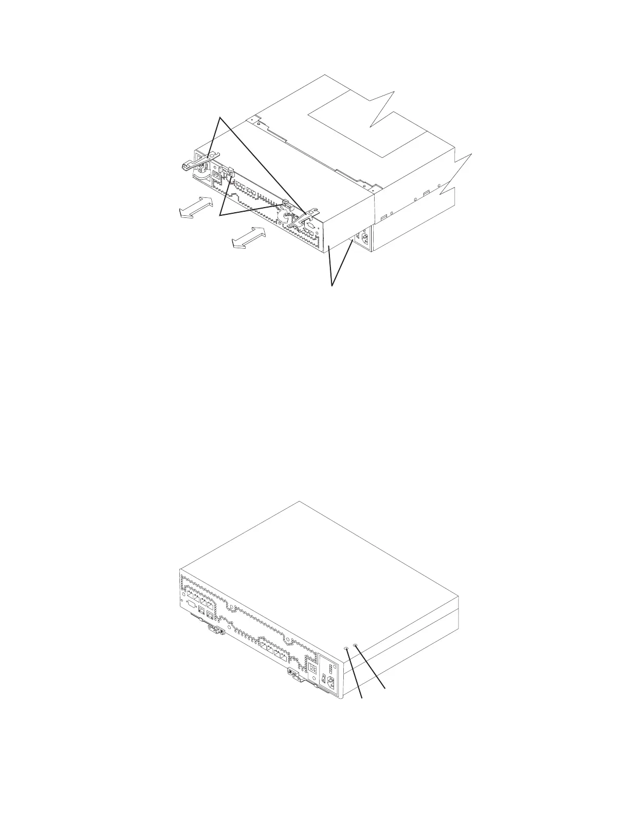
8. Insert a nonconducting stylus through the appropriate hole in the cover of the
controller and press down gently. One hole is over the AC circuit breaker, a
second hole is over the DC circuit breaker. (DC is not currently supported for
the DS4800.) Figure 82 shows the location of the circuit breaker access holes
in the controller B cover.
Note:
When controllers A and B are inserted in their respective controller slots
in the DS4800, the location of the circuit breaker access holes are as
follows. On controller A, the circuit breaker access holes are located on
the left side on the bottom of the controller. On controller B, the circuit
breaker access holes are located on the right side on the top of the
controller (as shown in Figure 82).
RAID controllers
Levers in released
position
Latches
ds48045
Figure 81. Removing the controller from the storage subsystem
AC circuit breaker
DC circuit breaker
ds48044
Figure 82. Circuit breaker access holes
Chapter 4. Operating the storage subsystem 135