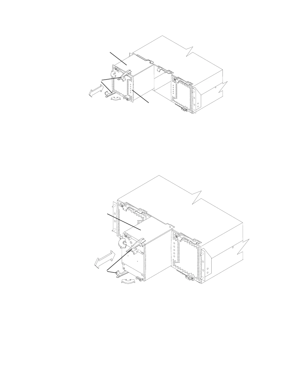
2. Replace the interconnect-battery unit. Figure 22 shows the location of the
interconnect-battery unit and the interconnect-battery unit levers.
The interconnect-battery unit is keyed to always fit into the enclosure in the
proper orientation. A large pin located on the back of the component prevents
the component from being installed incorrectly. Before installing the component,
turn the component so that the LEDs are near the top of the component.
3. Replace the controllers at the back of the DS4800. Figure 23 on page 46 shows
the location of the controllers and the controller levers. Ensure that controller A
is returned to the upper slot and that controller B is returned to the lower slot.
Note:
Controller B is installed in an orientation that is rotated 180 degrees from
that of controller A.
Power supply-fan
Levers in
released
position
Indicator LEDs
ds48030
Figure 21. Replacing the power supply and fan units
Levers
in released
position
Interconnect-
battery unit
ds48017
Figure 22. Replacing the interconnect-battery unit
Chapter 2. Installing the storage subsystem 45