EXP100. Continue this cabling pattern until you encounter an EXP710 or
EXP810, then cable from the IN port on the left ESM (ESM A) of the EXP100 to
the IN port of the EXP710 or EXP810.
v If an EXP710 or EXP810 follows the initial EXP100, cable from the IN port on the
left ESM (ESM A) of the EXP100 to the IN port of the EXP710 or EXP810. To
cable to the next storage expansion enclosure in the chain, cable from the OUT
port of the left ESM of the EXP710 or EXP810 to the IN port of the next storage
expansion enclosure.
v Continue the left ESM (ESM A) cabling pattern by cabling from the OUT port to
the IN port on subsequent storage expansion enclosures until you complete the
chain.
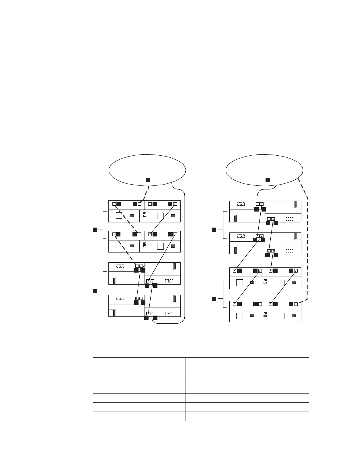
Figure
56 shows an acceptable EXP710, EXP810 and EXP100 intermix
configuration in a DS4800 environment. The cabling is acceptable because it
follows the cabling recommendations.
Table 25. Description of Figure 56
Number Description
1 DS4800 Storage Subsystem
2 EXP100
3 EXP810
4 IN port
5 OUT port
6 Port 1B
ESM B
ESM A
ESM BESM A
ESM BESM A
ESM BESM A
ESM B
ESM A
ESM BESM A
Out
ESM B
ESM A
ESM B
ESM A
1 1
22
2
3
3
4
5
4
5
4
45 5
6
7
6
7
6
7
7
6
6
7
7
6
6
7
7
6
4
45 5
4 4
5 5
exp100810a
Figure 56. Acceptable EXP710, EXP810 and EXP100 intermix configuration in a DS4800
environment
82 IBM System Storage DS4800 Storage Subsystem: Installation, User’s, and Maintenance Guide
|
|
|
|
|
|
|
|
|
|
|
|
|
|
|
|
|
|
|
|
|
||
||
||
||
||
||
||