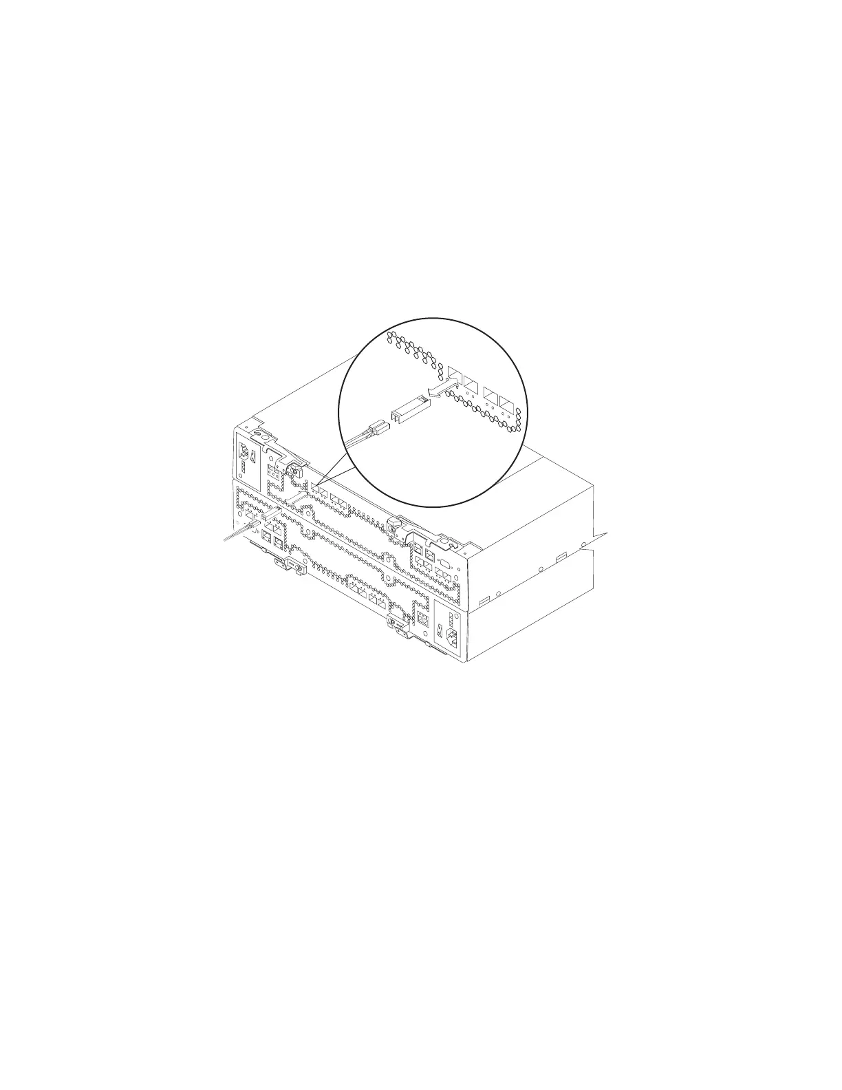
3. Remove the protective cap from the fibre channel port. Save the protective cap
for future use.
4. Insert the SFP module into the fibre channel port until it clicks into place. See
Figure 26.
Note: The alignment of the fibre channel ports on controller A are opposite
those of controller B. Before inserting an SFP module into a port, verify
that the SFP module is rotated correctly to match the alignment of the
port on the RAID controller. Do not force-fit. For fibre channel ports in
controller A, SFPs should be inserted with the exposed printed circuit
facing up (as shown in Figure 26). For fibre channel ports in controller B,
SFPs should be inserted with the exposed printed circuit facing down.
5. Connect a fibre channel cable.
Removing SFP modules
To remove the SFP module from the fibre channel port, perform the following steps.
Attention: To avoid damage to the cable or to the SFP module, make sure you
unplug the LC-LC fibre channel cable before you remove the SFP module.
1. Remove the LC-LC fibre channel cable from the SFP module. For more
information, see “Handling fiber-optic cables” on page 48.
2. Unlock the SFP module latch:
v For SFP modules that contain plastic tabs, unlock the SFP module latch by
pulling the plastic tab outward 10°, as shown in Figure 27 on page 51.
ds48031
Figure 26. Replacing an SFP module
50 IBM System Storage DS4800 Storage Subsystem: Installation, User’s, and Maintenance Guide