After you select the cabling topology for your configuration, continue with step 3,
following the cabling diagram for your chosen topology.
3. The following steps describe the cabling sequence for connecting at least two
storage expansion enclosures to a DS4800 using the preferred topologies
identified in “DS4800 Storage Subsystem drive cabling topologies” on page 69.
Note: If you are not using the preferred cabling topology, or if you are only
connecting one storage expansion enclosure to the DS4800, your cabling
sequence will differ from the following steps.
For either EXP100 or EXP710 storage expansion enclosure connections:
Perform the following steps to cable either the EXP710 or EXP100 storage
expansion enclosures to each other and to the DS4800.
Note: If you are intermixing different storage expansion enclosures such as
EXP100s, EXP710s, and EXP810s in a DS4800 configuration, refer to
the intermixing cabling diagrams provided in “DS4800 Storage
Subsystem drive cabling topologies” on page 69.
You can match the connections describing these steps with the cabling diagram
(provided in “DS4800 Storage Subsystem drive cabling topologies” on page 69)
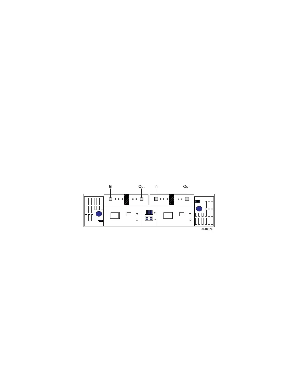
that most closely matches your configuration. Figure 43 shows the name of the
ESM ports in the EXP710 /EXP100 storage expansion enclosures.
a. Starting on the DS4800 controller, connect drive port 4 (drive channel 1) of
controller A to the In port on the left ESM board of the first storage
expansion enclosure in the group. (See callout 1 in Figure 44 on page 64.)
b. From the first storage expansion enclosure that will be cabled together
behind a drive port of a drive channel, connect the Out port on the left ESM
board to the In port on the left ESM board of the second (next) enclosure.
(See callout 2 in Figure 44 on page 64.)
c. From the first storage expansion enclosure, connect the Out port on the right
ESM board to the In port on the right ESM board of the second (next)
enclosure. (See callout 6 in Figure 44 on page 64.)
d. If you are cabling more storage expansion enclosures to this group, repeat
the In port to Out port connections until you reach the last storage
expansion enclosure. (See callouts 3 and 4 for the left ESM connections
and callouts 7 and 8 for the right ESM connections in Figure 44 on page
64.)
Figure 43. EXP710 /EXP100 port labels
Chapter 3. Cabling the storage subsystem 63