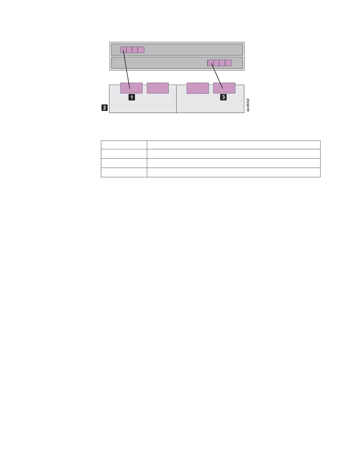
Table 18. Description of Figure 48
Number Description
1 Drive channel 1
3 Drive channel 3
2 Enclosure 1
1. To create drive channel 1, connect drive port 4 of controller A to enclosure 1
(2).
2. To create drive channel 3, connect drive port 1 of controller B to enclosure 1
(2).
One DS4800 and two storage expansion enclosures
If you are cabling one DS4800 Storage Subsystem to two storage expansion
enclosures, Figure 49 on page 72 shows the recommended cabling schemes.
As Figure 49 on page 72 and Figure 50 on page 73 show, when you connect
additional storage expansion enclosures, you can connect them either by using the
additional port of the drive channel or by continuing the connection from the existing
redundant drive channel pair. View 1 is the recommended cabling topology; View 2
is a possible cabling topology, however, it is not recommended.
Figure 48. One DS4800 and one storage expansion enclosure — Recommended cabling
Chapter 3. Cabling the storage subsystem 71