– Flashing slowly (once per second): The server is turned off and is ready to
be turned on. You can press the power-control button to turn on the server.
– Lit: The server is turned on.
– Fading on and off: The server is in a reduced-power state. To wake the
server, press the power-control button or use the IMM web interface. See
“Logging on to the Web interface” on page 87 for information on logging on
to the IMM web interface.
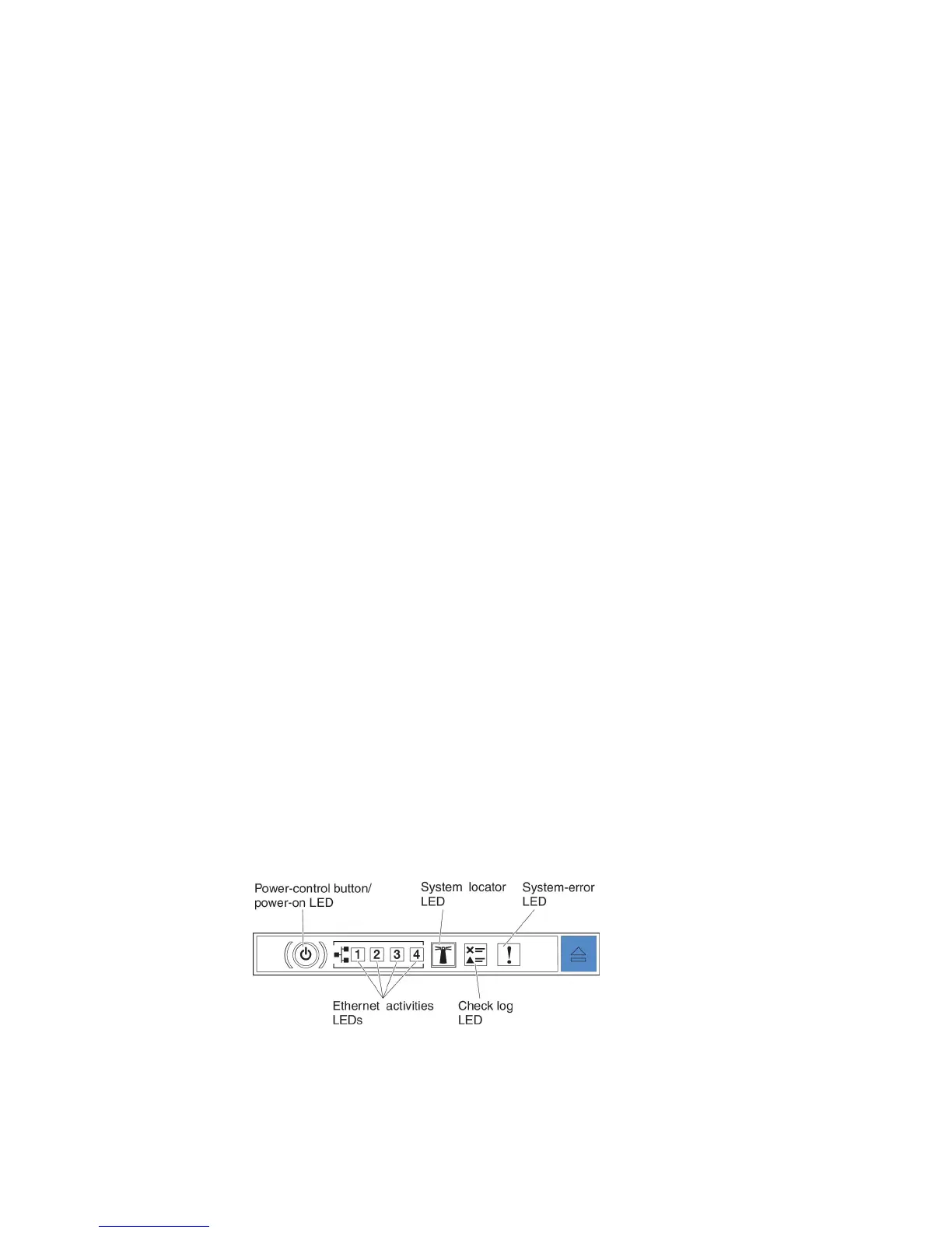
v Ethernet activity LEDs: When any of these LEDs is flashing or flickering, it
indicates that the server is transmitting to or receiving signals from the Ethernet
LAN that is connected to the Ethernet port that corresponds to that LED.
v Locator button/LED: Use this blue LED to visually locate the server among
other servers. This LED is also used as a presence detection button. You can use
IBM Systems Director to light this LED remotely. This LED is controlled by the
IMM. When you press the locator button, the LED will be lit and it will continue
to be lit until you press it again to turn it off. Press the locator button to visually
locate the server among the others servers. It is also used as the physical
presence for the Trusted Platform Module (TPM).
v Log LED: When this yellow LED is lit, it indicates that a noncritical event has
occurred. Check the system-event log for additional information. See “Error
messages” on page 122 for more information about event logs.
v System-error LED: When this yellow LED is lit, it indicates that a system error
has occurred. A system-error LED is also on the rear of the server. An LED on
the light path diagnostics panel on the operator information panel is also lit to
help isolate the error. This LED is controlled by the IMM.
v Reset button: Press this button to reset the server and run the power-on self-test
(POST). You might have to use a pen or the end of a straightened paper clip to
press the button.
Note: All the operator information is on the operator information panel already.
You do not need to pull the panel out for obtaining more information.
Light path diagnostics panel
The light path diagnostics panel is available on the top of the advanced operator
information panel. For additional information about the light path diagnostics and
LEDs on the light path diagnostics panel, see “Light path diagnostics” on page 106
and “Light path diagnostics LEDs” on page 109.
The following illustration shows the optional advanced light path diagnostics
panel.
16 System x3530 M4 Type 7160: Installation and Service Guide