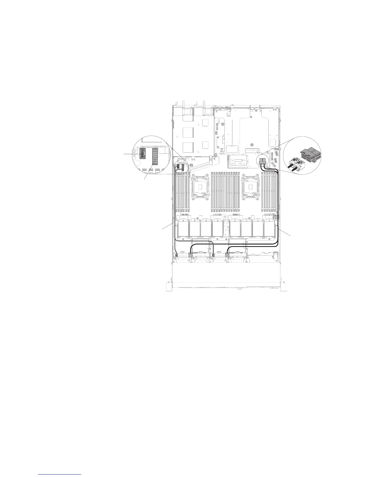
4. Connect the signal, power and configuration cables to the system board. Route
the signal cable from the drive backplane along the chassis and connect it to
the SAS/SATA controller connectors. Then, route the power cable and the
configuration cable from the drive backplane along the chassis and connect it to
the SAS/SATA power connector and SAS/SATA configuration connector. The
following illustration shows the cable routing and connectors for the 2.5-inch
and 3.5-inch hot-swap backplanes.
SAS/SATA configuration
and power cable
SAS/SATA signal
cable
SAS/SATA power
connector
SAS/SATA
configuration
connector
Figure 123. 8 x 2.5-inch hot-swap backplane cable connection
206 IBM System x3550 M5 Type 5463: Installation and Service Guide
 Loading...


